
LJLogUD is a simple ready-to-run executable that logs up to 16 input channels from a single device. It displays selected channels on a graph and writes data to file. Generally used for ≤100 scans/second.
Just starting? See our Device Quickstart Tutorials, then our LJLogUD Basics Guide.
Supported devices
-
U3
-
U6
-
UE9
Download
The application LJLogUD is included with the main installation package.
For LabVIEW programmers, the source code is available in the LabVIEW_LJUD archive.
Subsections
Overview
LJLogUD uses command-response mode which is typically used at 100 scans/second or slower. See Section 3.1 of the applicable user's guide for details about command-response data rates. Also see the analog input section (2.x).
LJLog vs. LJStream: We suggest that you use LJLogUD if possible, and only if you need to go too fast for LJLogUD do you then switch to LJStreamUD. LJLogUD uses command-response mode, so it acquires and processes 1 scan at a time at the specified interval and is generally used for ≤100 scans/second. LJStreamUD uses stream mode, so each iteration it retrieves and processes 1 seconds worth of scans and is generally used for >100 scans/second. For more discussion of command-response mode and stream mode see Section 3.0 of the applicable user's guide: U3, U6, or UE9.
LJLogUD vs. LJLogM: LJLogUD supports the U3, U6, and UE9. LJLogM supports T-Series devices.
Clearing Errors: Errors such as bad program settings can break the typical program execution. In most cases these errors can be cleared without exiting LJLogUD by using the Configuration panel.
-
Opening the configuration panel will clear the current error. The next program loop will run error free, however note that this will only resolve one-time errors.
-
Some device connection issues can be resolved by opening a new device connection using the
Configurationpanel. If you run into a device connection issue, try using the "ANY" connection options for every setting. This will attempt to open the first found UD-compatible LabJack device that is visible to the computer. -
Bad program configurations can be cured by loading the default program config file
LJUD_Default_Configs.cfgusing theConfigurationpanel.LJUD_Default_Configs.cfgis saved to the current working directory each time LJLogUD is opened.
See the “Default Configuration Files” and “Configuration Panel” sections below for more information.
Default Configuration Files
LJLogUD generates the following configuration files in the current working directory. None of these files should be modified outside of the program:
-
LJLogUD.cfg: Contains logger control configurations such as
# Channels,Ch+, what channels to Graph, etc. This is a file that the program loads on startup, and it is the file that your control configurations are saved to when you close the program. -
LJLogUD_open.cfg: Contains device open settings (DeviceType, ConnectionType, Identifier). This is a file that the program loads on startup.
-
LJUD_Default_Configs.cfg: Contains the default program configurations for
LJLogUD.cfg. These are the configurations you would see when you load the program for the very first time. If there is some issue withLJLogUD.cfgand you want to start from a known working configuration, load this file as your program configuration using the configuration button(s). See the “Configuration Panel” section below for more information about loading a configuration file.
Startup and Shutdown Behavior
When the program is started, the configuration file LJLogUD.cfg is read to determine the starting program configurations. If there is a problem loading the program configuration file, default configurations will be loaded. LJLogUD_open.cfg is read to determine the starting LabJack device open configurations. Any errors that occur when trying to open a device connection will be displayed under Error Message. A new device connection can be made at any time using the Configuration button; see the “Configuration Panel” section below.
When you exit the program, the current program settings are saved to LJLogUD.cfg and device open configurations are saved to LJLogUD_open.cfg. These files are saved to the current working directory, which will also be loaded the next time LJLogUD is opened.
Control and Indicator Descriptions
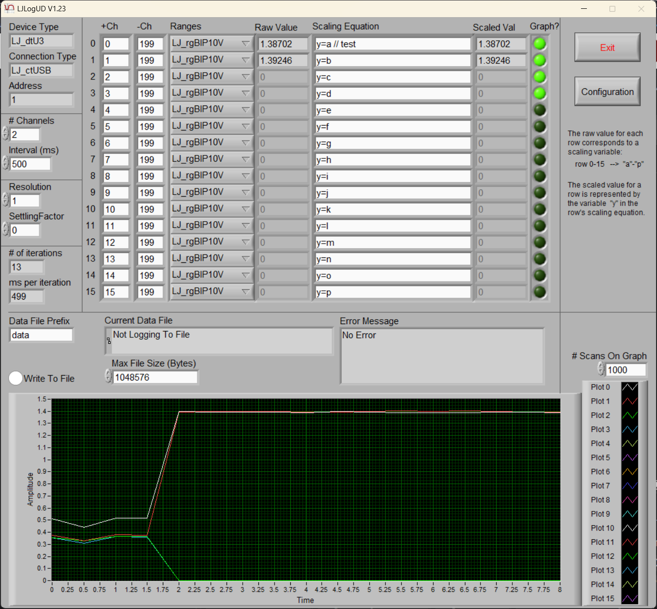
Device Type, Connection Type, and Address (Opening): These indicators display information about the device connection that has been claimed by the program. By default the program will open the first device connection it can find. To make a new device connection, click the Program Configuration button then use the “Open a New Device Connection” options to make your desired connection. When you exit the Configuration panel and LJLogUD, the connection options you chose will be loaded the next time LJLogUD is opened.
Getting errorcode 1007? That means LJLogUD can't find the device it is looking for. The most common issue is that some other process (e.g. LJControlPanel) has the device open and thus LJLogUD can't claim it.
# Channels: 1-16. Determines the number of rows/channels that will be measured. For example, row0, row1, and row2 will be active and measured if # Channels=3.
Interval (ms), ms Per Iteration: Interval (ms), also referred to as the scan[1] interval, is the time interval in which program will attempt to complete a scan of data, update the screen, and log data to file (when logging is enabled). Note: It is possible for each logger iteration to take longer than the desired scan interval. The ms Per Iteration indicator describes the actual time interval measured for the last iteration of the program.
Resolution: For the U3, a value of 0 disables QuickSample and a value of 1 enables QuickSample. See Section 3.1 of the U3 User's Guide for how this affects speed and Appendix A of the U3 User's Guide for how this affects noise. The U6 expects resolution settings from 0-12 while the UE9 expects settings from 0-18. A value of 0 equates to 8 on a U6, 9 on a U6-Pro, and 12 on a UE9. To see how this setting affects speed and noise see Section 3.1 (U6 or UE9) and Appendix B (U6 or UE9) of the applicable user's guide.
SettlingFactor: This parameter affects settling time, which is the time allowed for the analog input voltage to settle after switching from one channel to another. For the U3, a value of 0 disables LongSettling and a value of 1 enables LongSettling. See Section 3.1 of the U3 User's Guide for how this affects speed and Appendix A of the U3 User's Guide for how this affects max source impedance. For the U6, a value of 0 means Automatic which provides settling sufficient for at least 1k of source impedance. The times from Section 3.1 of the U6 User's Guide are measured with a SettlingFactor of 0. All allowed values are 0=Auto, 1=20us, 2=50us, 3=100us, 4=200us, 5=500us, 6=1ms, 7=2ms, 8=5ms, and 9=10ms. For the UE9, settling time is discussed towards the end of Section 2.7.0 of the UE9 User's Guide, and a SettlingFactor of 0-255 is multiplied by 5 microseconds to determine an amount of extra settling time added to the normal settling time.
# of Iterations: The number of sampling iterations that have occurred since the program was started or the configuration panel was used to select new configuration options.
+Ch/-Ch: +Ch is short for Positive Channel and -Ch is short for Negative Channel. LJLogUD is designed to read the voltage from analog input channels. Voltage is the potential difference between 2 points, thus in each row you need to specify the 2 points. For example, the default values for the first row are +Ch=0 and -Ch=199, which means the device will do a single-ended (versus GND) read of AIN0.
There are special analog input channel numbers that allow you to read other types of channels (DI, Timers, Counters). See the special channel support described in Section 3.2.1 or 3.2.2 (stream mode section) of the applicable User's Guide.
For example, if you have a U3 and you want to read/log the state of the FIO & EIO lines, type the value 193 into the +Ch cell and you will read a 16 bit number that contains the state of all 16 I/O lines.
You can put any channel in any row. For example, you could set the first row to +Ch=5 and -Ch=199 to do a single-ended read of AIN5, or you could set the first row to +Ch=201 to do a read of Timer1 (assuming Timer1 has been enabled, -Ch does not matter).
Ranges: Select the desired range, which is related to gain. Not all devices support all ranges, but starting with UD V3.19 the best range available (next higher range) will be selected rather than throwing an error.
The U3 does not support any range settings, so any value can be used.
Valid U6 Ranges:
-
LJ_rgBIP10V: ±10 V i.e. Gain=x1 -
LJ_rgBIP1V: ± 1 V i.e. Gain=x10 -
LJ_rgBIPP1V: ±0.1 V i.e. Gain=x100 -
LJ_rgBIPP01V: ±0.01 V i.e. Gain=x1000
Valid UE9 Ranges:
-
LJ_rgUNI5V: 0-5 V, LabJackUD Default -
LJ_rgUNI2P5V: 0-2.5 V (not supported with resolution=18) -
LJ_rgUNI1P25V: 0-1.25 V (not supported with resolution=18) -
LJ_rgUNIP625V: 0-0.625 V (not supported with resolution=18) -
LJ_rgBIP5V: ±5 V
Note: due to the way this program and the UD driver parse the channels list, all rows with the same number in +Ch will use the range set by the last row with that same +Ch.
Raw Value: The value read from the channel entered in the Ch+ column for the row.
Scaling Equation: Scaling equation applied to the raw value for the row. This scaled value is reported in the Scaled Val column. The raw value for each row is mapped to a variable as follows:
row 0-15 → "a"-"p"
For example, the default scaling equation for row0 is y=a, where y represents the scaled output value and a is a variable representing the raw value of the row.
Everything in the scaling equation after the characters // is ignored if you want to add comments. Examples:
y=c // Scaled value equal to raw value from 3rd row
y=100*c // EI-1034/LM34 voltage to deg F
y=c-273.15 // deg K to deg C
y=((c-273.15)*9/5)+32 // deg K to deg F
y=TCVoltsToTemp[K:c:a] // Type K, t/c voltage from 3rd row, CJ temp from 1st row
For more details see the LJLog/Stream Scaling Equations page.
Scaled Val: The value calculated from the scaling equation for the row. See Scaling Equation above.
Graph?: Determines whether the channel is graphed. The channel is graphed if the Graph? button is selected (lit up green) and the row is active according to the # Channels value.
Note: graphing many channels and using a large # Scans on Graph configuration can reduce performance and limit the program scan interval[1]. Limit the number of channels graphed to <20 or limit # Scans on Graph to help avoid these complications.
Data File Prefix: The program uses this as the base string when it makes a file name. When the program starts a new file, it appends a “_#” to the specified prefix, where "#" is the first unused number from 0-99999. For example, the default value for Data File Prefix is “data”. The first log file in an empty working directory would be named ‘data_0.dat’, the second log file would be named "data_1.dat", etc.
Log To File: When this button is selected, data will be logged to file. The resulting file is a tab-delimited ASCII-encoded file. Files are written with a .dat extension. To quickly open log files in Excel or Open Office Calc, change the extension to .xls or .ods. To import the file to a Google Spreadsheet, change the extension to .tsv before uploading.
At the top of the log file is a human readable system timestamp of when Log To File was enabled.
The first data column in the file is a timestamp of seconds since midnight January 1st (Universal Time), 1904. This timestamp is generated from the host computer, not the LabJack device. For more information about presenting this timestamp in Microsoft Excel or Open Office Calc, see the LJLogUD & LJLogM Timestamps page.
After the timestamp column are columns containing “raw” channel readings for each active channel followed by columns containing the scaled values for each active channel. Both raw and scaled values will be logged even if scaled = raw. For example if # Channels = 2, a line of data in the log file would look similar to the following:
Timestamp Raw0 Raw1 Scaled0 Scaled1
Note: LJLogUD versions 1.22 and earlier only log the scaled values, not “raw” channel readings.
Each row of logged data requires roughly 18 bytes for the timestamp plus 11 bytes per channel. If you log 8 channels, once per second for 60 seconds, you could expect a file size of approximately (18 + 11*8) * 60 = 6360 bytes. A 1 TB hard drive could hold a few hundreds of years of this data.
Max File Size (Bytes): When the current data file exceeds this limit, the file is closed and a new file is started. See the Data File Prefix description above for information on file naming conventions.
Current Data File: This indicator shows the path to the current file that data is being written to. When Log to File is not enabled, this indicator will say ‘Not Logging To File’.
Error Message: This indicator shows any errors that occurred in the most recent program iteration. Error messages will be displayed if there are UD driver or scaling equation errors. If there are both UD driver and scaling equation errors, only the UD driver error message will be displayed. UD driver errors should be resolved as soon as possible. Note: when a scaling equation error occurs, the scaled value indicator for the channel will be set to zero.
Exit: This control will exit the program. It is the only way the program should be exited to ensure that device connection resources are released and configurations are saved properly.
Configuration: The Configuration button opens a panel with program configuration options. See the “Configuration Panel” section for more information.
# Scans on Graph: Controls how many scans[1] are shown on the graph. For example, if you set this value to 120 and you acquire 2 scans/second (a scan interval of 500ms) the graph will show 60 seconds of data. The graph is similar to a strip chart, and it displays the last n scans. To clear the graph, change any entry in the Graph? array of buttons.
Configuration Panel
The configuration panel has controls to open a new device connection, change the program working directory, and save or load program configurations from file. The panel can be opened by clicking the Configuration button near the center-right of the main program window. Note: opening the panel stops channel acquisition and logging until the panel is closed.
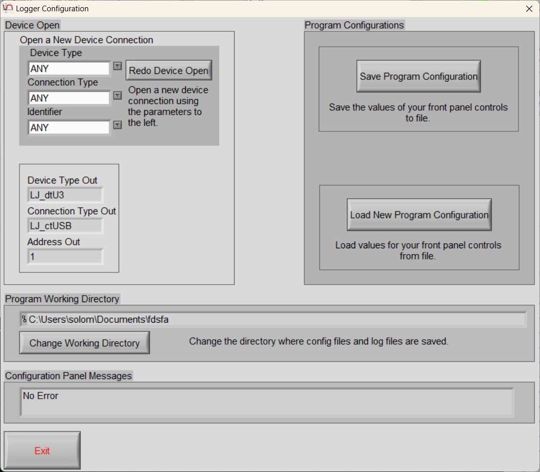
Open a New Device Connection: The “Open a New Device Connection” section can be used to open a different device connection. Change each of the Device Type, Connection Type, and Identifier fields then click Redo Device Open to attempt to open a new device connection. If the connection fails, an error message will be displayed and the previous device connection will be reestablished as long as the connection is still valid. If you successfully open a new device connection, the new device connection details will be displayed and later saved to LJLogUD_open.cfg upon closing the program.
Program Working Directory: The “Program Working Directory” section displays the current working directory for the program. This determines the location of the program configuration file and where log files are saved.
The Change Working Directory button can be used to change the current working directory where program configuration files and log files are saved. After navigating to the desired directory in the pop-up window, click Select Cur Dir at the bottom-right. For more details see the LJLog/Stream Working Directory page.
Program Configurations: The “Program Configurations” section allows you to save the current program configuration to file or load a configuration from an existing program configuration file. New program configuration files are saved to the current working directory; see the “Program Working Directory” section. Program configuration files save the following program controls: # Channels, Interval (ms), Resolution, SettlingFactor, Ch+/Ch-(for every row), Ranges (for every row), Scaling Equation (for every row), Graph? (for every row), Data File Prefix, Log to File, Max File Size (Bytes), and # Scans on Graph configurations.
Configuration Panel Messages: Any errors that occur while attempting to make changes in the configuration panel will be displayed in the “Configuration Panel Messages” section. Messages are also displayed upon successful configuration changes.
Experimental LJLogUD v2.0
An experimental version of LJLogUD that supports up to 84 logger channels is available here: LJLogUD84.exe.
There are a few notable control differences.
Alternate Channel Names: Channels can be named in an alternative format to allow for easy mapping of AIN channels to connections when using both a Mux80 AIN Expansion Board and one or more CB37 Terminal Boards. The alternative channel naming convention is to type the Mux80 connection terminal name followed by a dash and then the CB37 channel name. For example, a channel named X4-FIO6 would correspond to the signal from the FIO6 channel on a CB37 connected to the X4 terminal on a Mux80. This would lead to exactly the same behavior as entering 94 for the channel name as this channel corresponds to AIN94. For more information on mapping signals from Mux80/CB37 connections to AIN channels, see Table 1 in the Mux80 Datasheet.
Pages: 5 additional pages of controls are added for Mux80/CB37 support, allowing for reads of up to 84 channels at once. By default Page 1 will perform a single-ended read of AIN0-AIN15, similar to older versions of LJLogUD. Pages 2-6 by default will perform single-ended reads of various channels for Mux80/CB37 connections in the alternate channel name format described above.
Scaling Equation: Input voltage variables for Page 2 through Page 5 are a through p with their page number appended. For example, page 2 has the input voltage variables a2 through p2.
Log To File: This version of LJLogUD only logs the scaled values, not “raw” channel readings.
Revision History
1.04: Not compatible with older config files, so delete ljlogud.cfg before running the first time! Changed config file delimiter to "#!#" instead of "," for better international compatibility. Made maximum file size a user control.
1.05: Turned on scroll bars, for use on smaller monitors.
1.06: No longer disables timers and counters. Makes error display red if there is an error.
1.07: Fixed the jumbled looking screen in Windows 7. Fixed problem where Ch- was not set to analog resulting in errorcode #16.
1.12: Added support for registry storage of working directory. Fixed problem where Graph History setting was not remembered. Comments now allowed in scaling equations starting with "//".
1.15: Two changes. The first is that it now supports a config file that lets you specify a particular device to open. See the description of "Device Type & Address" above. The second is that it now uses the filename of the application to specify the names of the config files and to specify the location of the working directory registry key. The former means if you make a copy of LJLogUD.exe called LJLogUD2.exe, the config files will be LJLogUD2.cfg and LJLogUD2_open.cfg and thus each copy has its own config files. The latter means you can use a different working directory for each copy, although you don't have to.
1.16: Added "Write To File" control to items saved in config file, so the application will now remember how this control was last set.
1.17: Changed all text to Segoe UI font so screen items are aligned regardless of system font size. Changed to show scroll bars.
1.18: Added support for SignedLSWMSW[lsw:msw] function in scaling equations to handle quadrature reads. For efficiency, scaling equations now skipped if no scaling is needed (e.g. y=a).
1.19:Set minimum value of #Channels to 1. Fixed problem where name of the exe was not detected properly. Fixed issue where you could never decrease the number of channels shown on graph. Changed version check sub-vi so it only shows prompt when new version available ... not on version check errors.
1.20: Changed to grab the timestamp after data is read but before scaling is applied, rather than after scaling. Fixed problem where -Ch array was not handled properly when non-analog channels (193+) were used, resulting in other analog channels sometimes returning binary values.
1.21: Added additional pages to support up to 84 channels for Mux80/CB37 support. Added alternate channel naming convention to allow for easier mapping from names printed on Mux80/CB37 inputs to analog channel numbers. Added "Actual Interval (ms)" indicator to show how long each logging loop takes. Added configuration file selection and save options. Configuration files made in LJLogUD v1.21 are not compatible with old versions of LJLogUD if using the new alternate (string) channel names, but are compatible if numeric channel names are used.
1.22: Fixed SignedMSWLSW scaling equation functionality. This was previously returning an unsigned 32-bit integer representation. It now returns a signed 32-bit integer representation.
1.23: Reworked configuration file handling, including adding the configuration panel. Moved the 'Change Working Directory' button to the configuration panel. Refactored the write to file functionality. Added scaling equation error messaging. Renamed the 'experiment' configuration file to 'program' configuration file. Increased front panel text size, changed the font to Arial (monospace), set the minimum panel size, and other minor front panel UI changes.
Footnotes
[1] A scan consists of one sample from every channel in a scan list. As it relates to LJLogUD, a scan would consist of a sample from every channel (up to # Channels) in the Ch+ column.