T-series devices have various configurable clock sources as part of the Digital I/O Extended Feature (DIO-EF) system. In this example we will use the Kipling Register Matrix to configure an output for a PWM signal. For this example we use clock 0 with default settings. The clock source is the base for configuring PWM output. In this example we will set the frequency to 100 Hz and the duty cycle to 25%.
Before you begin
This example uses FIO0 (aka DIO0) which supports PWM output on the T7. Use FIO2 (DIO2) for the T8 and FIO6 (DIO6) for the T4.
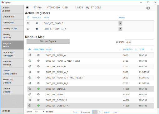
1. Go to the Register Matrix in Kipling and type "dio0" in the search box to narrow the list of registers. Add the ENABLE and CONFIG_A registers to the active list as shown in Figure 1.
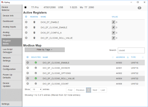
2. Change the search term to "clock0" and add the DIO_EF_CLOCK0_ENABLE and the DIO_EF_CLOCK0_ROLL_VALUE to the active list. The base clock frequency varies by device. On the T8 it is 100 MHz, on the T7 and T4 it is 80 MHz.
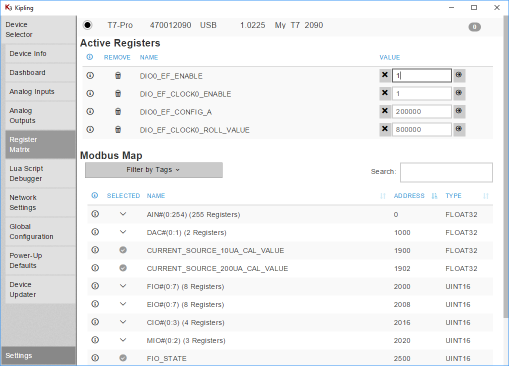
To get 100 Hz on the T4 and T7, we need to divide by 800000. Since our divisor is 1 (default), our roll value is 800000.
80 MHz / (1 * 800000) = 100 Hz
To get 100 Hz on the T8, we need to divide by 1000000. Since our divisor is 1 (default), our roll value is 1000000.
100 MHz / (1 * 1000000) = 100 Hz
To configure the duty cycle: 25% = 100 * Config_A / Roll_Value, so CONFIG_A is 200000 on the T4 and T7 or 250000 on the T8.
3. Write your configuration values, replacing DIO# with the DIO number you are configuring the feature on:
DIO#_EF_ENABLE = 0 // Cannot change index if enabled
DIO_EF_CLOCK0_ENABLE = 0 // Disable the clock for config
DIO_EF_CLOCK0_ROLL_VALUE = 800000 // On the T4 and T7. 1000000 on the T8
DIO#_EF_INDEX = 0 // PWM out index
DIO#_EF_CONFIG_A = 200000 // On the T4 and T7. 250000 on the T8.
DIO_EF_CLOCK0_ENABLE = 1 // Enable the clock
DIO#_EF_ENABLE = 1 // Enable the PWM
4. At this point the LabJack is outputting PWM on FIO0 at 100Hz with 25% duty cycle. To see the output, see the section below titled "Displaying PWM output in LJStreamM"
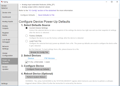
5. To save the configuration, so the PWM will be configured at boot-up, go to the Power-Up Defaults tab and click Configure Power-up Defaults. Make sure that Current Device Settings option is selected. This is suggested if using LJLogM or LJStreamM, or other simple polling programs, but not needed if your software will do the configuration.
Troubleshooting
Touching a conductor to the top of the screw head of an un-clamped screw terminal is rarely a valid connection. The screw head is usually valid when the terminal is clamped, but the only guaranteed valid connection is to securely clamp a conductor inside the screw terminal.
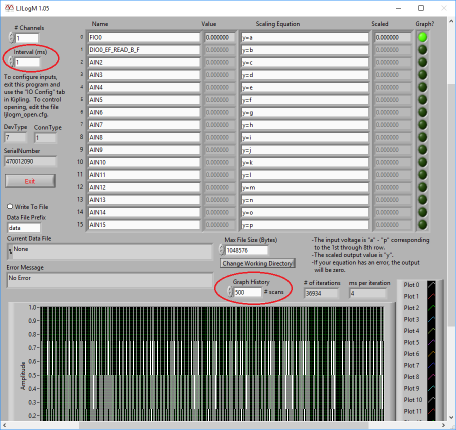
Displaying PWM in LJLogM
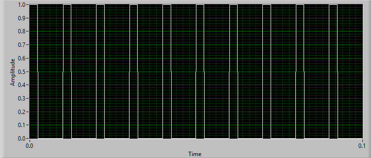
Once the PWM output is enabled (above), you can read FIO0 using any row in LJLogM. Change the interval to a low value such as 0 or 1, and the graph history to 500. The graph should display a PWM with 25% duty cycle.
LJLogM may take longer to read the signal than the desired interval setting, and it may not reproduce the PWM signal perfectly. Use LJStreamM at a high sample rate to view the waveform more clearly.
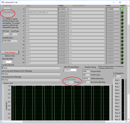
Displaying PWM in LJStreamM
Once the PWM is enabled (above), you can read FIO0 using any row in LJStreamM. Set the scan rate to 10000 Hz and the graph history to 1000 scans to see the PWM more clearly. Select Start Stream to begin graphing the PWM signal.
Configuring PWM in DAQFactory
To configure the counter you can use steps 1-5 above or write to the previously mentioned registers in DAQFactory. See "Device Configuration" on the DAQFactory for LJM page.
Configuring PWM in Your Program
The PWM pseudocode generator on the PWM Extended Feature page can be used to generate C-like pseudocode with the LJM function calls necessary to enable PWM. You can write PWM configuration registers individually using eWriteName, or all at once using eWriteNames.
The order of registers added to eWriteNames matters. Ensure that you configure the PWM registers in the order used by the PWM configuration examples (such as this page).