Stepper Motors
Stepper motors are a type of brushless DC electric motor that divides a full rotation into several discrete "steps" or positions that the motor can navigate to. This allows for positional control of the motor by delivering it a command to move a certain number of steps. The more steps in a rotation that a motor has dictates its resolution, and how precisely its movement can be controlled. The nature of stepper motors allows them to be used in systems where feedback from a rotary encoder is not possible. If the number of steps in one rotation is known, the motor can be moved any desired distance by calculating how many rotations and then how many steps that distance corresponds to. After being delivered this number of steps, the motor should move into the exact correct position.
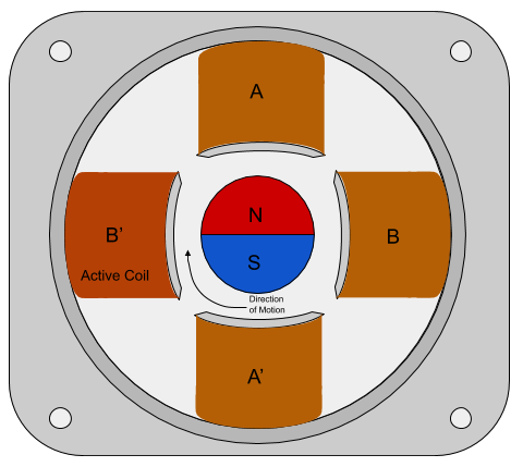
Stepper motors are generally composed of a gear that is connected to a motor shaft and surrounded by multiple electromagnets. These electromagnets are split up into groups that are called "phases". These phases alternate in a circle around the gear. Every electromagnet in a phase is energized at the same time and will pull the nearest tooth of the gear towards it. Once the gear has shifted to magnetically align with the electromagnets in the current energized phase it has effectively moved one "step". To move another step, this phase is turned off and the next phase in the sequence is powered on. This will again pull the teeth of the gear towards the next phase and turn the motor one step further. As each of these phases is energized independently of the other phases, generally each phase requires its own set of leads. Stepper motor controller programs and circuitry interpret the users command for how many steps the motor should move and dictate when to energize each phase accordingly.
Unipolar Vs. Bipolar Stepper Motors
In general, there are two types of stepper motors, Unipolar and Bipolar.
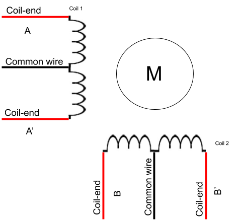
The most simple type of stepper motor is a two phase unipolar stepper motor. These have only two phases A and B that alternate around the metal gear. Each phase is composed of a single coil and a "center tap" or "common wire". The two coil ends and the center tap make three leads for each phase, with six leads total for the two phases. This arrangement allows the direction of the magnetic pole of each coil to be switched with one switch or two transistors per coil to determine which coil end will have current run through it. This allows the direction of the magnetic pole of each coil to change without the need for reversing current direction. The switching function can be facilitated with our PS12DC Power Switching Board or our LJTick-Relay Driver, which will only be useful for unipolar motors as bipolar stepper motors require more complex circuitry.
Bipolar stepper motors also have one coil per phase, but they do not have a center tap. The lack of center tap makes it so that bipolar stepper coils can only have the direction of their magnetic poles reversed by reversing the direction of the current in the coil. This is usually done by having one H-bridge circuit per coil. By turning on two of the four transistors in the H-bridge at a time, the user can programmatically change the direction of the current flow and by extension, the magnetic pole of each coil.
Stepper Motor Control Basics
There are many ways to control stepper motors, and the leading bleeding-edge control methodologies continue to advance. A few that exist are:
-
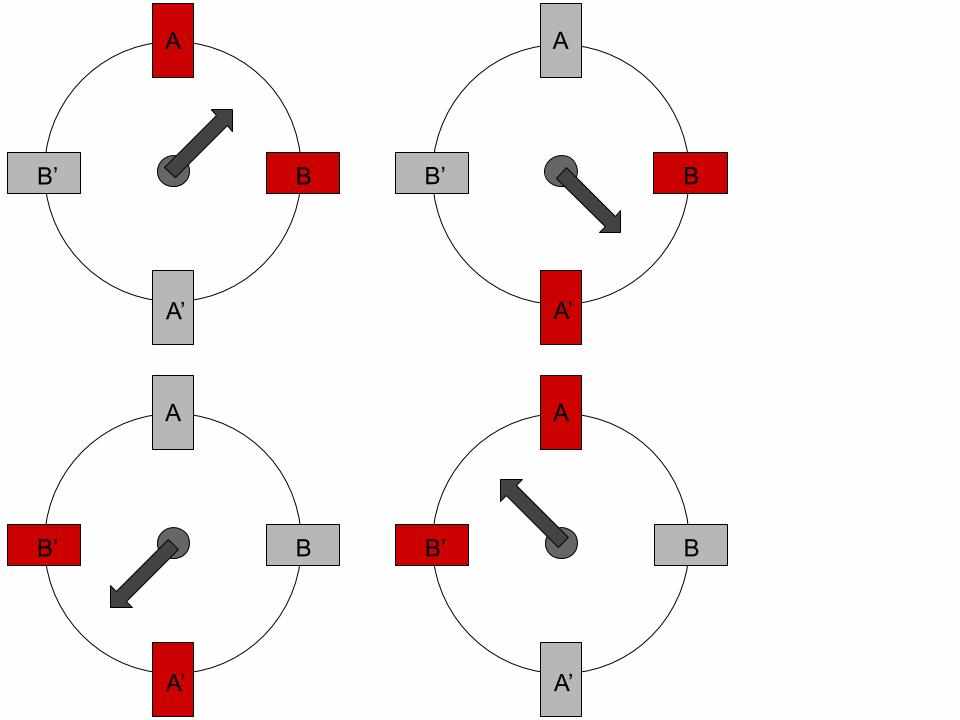
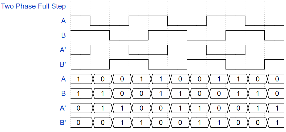
Full Step Drive: There are two basic types of full step drive, both with advantages and disadvantages:
-
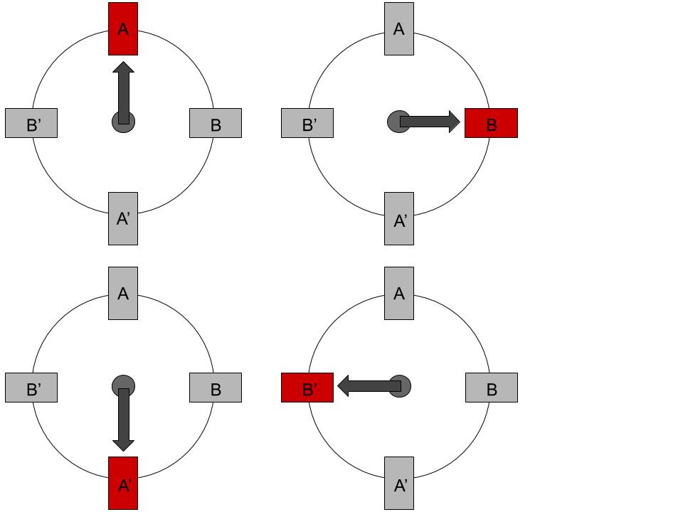
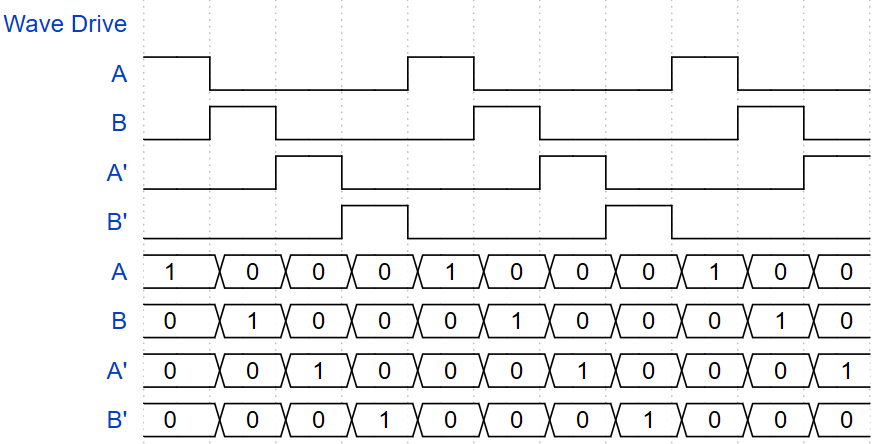
One Phase On - Full Step Drive: Also called Wave Drive mode, in this mode only one phase is energized at a time. This is the most simple mode of stepper control and it also requires the least amount of power.
-
Two Phase On - Full Step Drive: In this mode, two phases are energized at a time with the same amount of resolution as one phase on. However, because two phases are on at once this mode offers more torque at the cost of requiring more power than the other control modes.
-
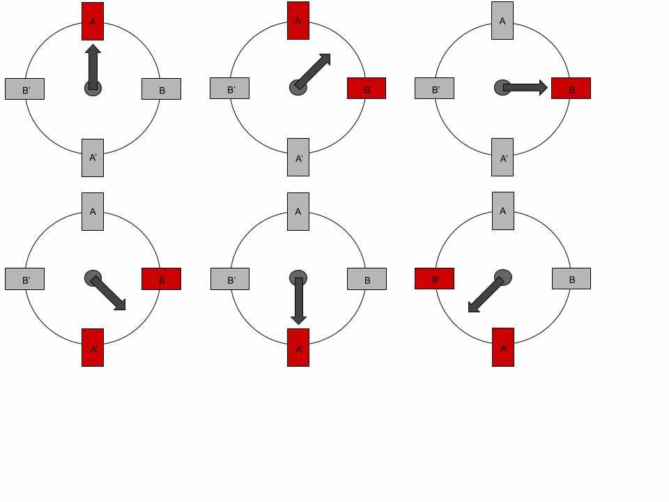
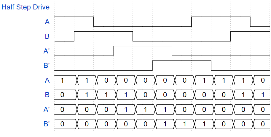
Half Step Drive: In this mode, the motor alternates between having one and two phases energized at a time. This allows half step to have twice the resolution as full step. This mode also "evens out" the advantages and disadvantages of one phase on and two phase on full step. Since two phases are on half of the time, half step mode will have more torque but use more power than one phase on full step and will have less torque but use less power than two phase on full step.
-
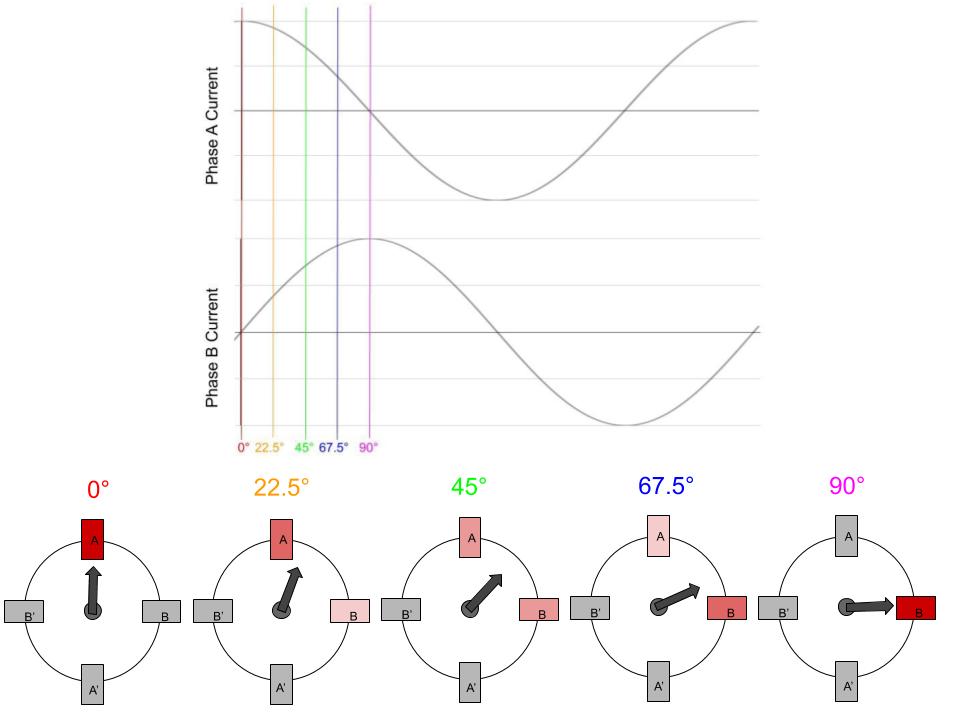
Micro Stepping: In this mode, two sine waves that are 90° out of phase with each other are delivered to the two phases of the motor. Because the two sine waves are 90° out of phase, the next motor phase will slowly become more energized at the same rate as the previous motor phase becomes less energized. This allows many small steps to be taken between the motor phases. Thus, this mode has vastly improved resolution and thereby generally offers much smoother and quieter motor operation than the other modes.
If higher precision or torque is required, advanced control capabilities that integrate digital signal processors (DSPs) also exist. There are also closed-loop control stepper motor systems that use rotary encoders as feed-back mechanisms that enable more precise rotation control or rotary shaft "hold" algorithms. Additional explanations about how stepper motors are controlled can be found through the links in the further reading section.
This app-note highlights the capabilities of LabJack devices being able to control stepper motors by using the one phase on full step (wave drive) and half step drive modes through running a Lua Script. These scripts are available through the Lua Script Examples section of our website or in Kipling and are titled unipolar_full_step.lua and unipolar_half_step.lua.
Connecting a Stepper Motor to a T-Series LabJack
Equipment
To successfully wire and operate a stepper motor using a LabJack you will need the following materials:
-
Computer with USB, Ethernet, or WiFi
-
Unipolar stepper motor
-
The PS12DC can handle 750mA per channel up to 28V, so most NEMA17 unipolar stepper motors will work. Always verify motor ratings with PS12DC datasheet.
-
Bipolar motors will not work, as they require 2 sets of H-Bridges, and the PS12DC is only a high-side switching device since it uses P-Channel MOSFETs.
-
Power supply
-
Here we will be using 12VDC, but anything that will not exceed the PS12DC ratings will work.
-
-
Hookup wires
Basic Connections
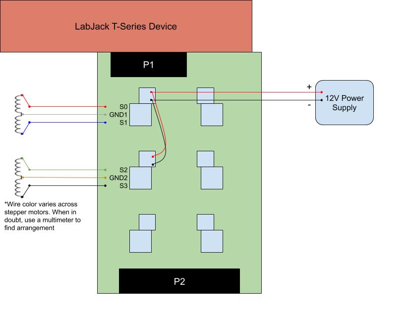
First connect the PS12DC to your LabJack as described in the PS12DC datasheet. As discussed above, an average two phase unipolar stepper motor should have a total of six leads, with two coil ends and the center tap for each phase. Connect the two coil ends of one of the phases to S0 and S1 on the PS12DC and connect the center tap of the coil to GND1. Similarly, connect the two coil ends of the other phase to S2 and S3 and connect the center tap of the second phase GND2. Then, connect VS1 to VS2 and connect GND1 to GND2. Finally, connect VS1 to the positive terminal of a 12V power supply and connect GND1 to the negative terminal of a 12V power supply.
NOTE: Any pair of S channels that are in the same block of the PS12DC can be used and have the same operation. The default LUA scripts unipolar_full_step.lua and unipolar_half_step.lua utilize S0+S1 and S4+S5 as the I/O channels, so make sure to update the LUA script with your application specific S channels before loading and using it.
Each of the S channels of the PS12DC corresponds to a LabJack digital I/O line. By setting the corresponding I/O line of a given S channel high, the 12V from the power supply will be directed through that S channel. Thus the user can programmatically choose when to fully energize each coil end through simple I/O line toggling. S0:S7 correspond to EIO0:EIO7 and S8:S11 correspond to CIO0:CIO3.
Another option for the power switching commutation circuit is our LJTick-RelayDriver (LJTRD). The LJTRD can be plugged into a LabJack with its INA/INB terminals connected to any digital I/O lines as seen in the LJTick-Relay Driver Datasheet. Then, the power and ground of the power supply can be connected the VR and GNDR terminals of the LJTRD. Now, similar to the PS12DC, the digital I/O lines can be set high to close the solid state switch within the LJTRD and direct the voltage from the power supply to the corresponding RA/RB terminal. If the coil ends of a phase are attached to these RA and RB terminals, the LJTRD will allow the user to decide when to fully energize each phase. Any other solid state relay or transistor with similar function and ratings can also be used.
Identifying Leads
A multimeter can be used to identify the leads of each phase as either a coil end or a center tap. One way to do this is by measuring the resistance between different pairs of leads. The resistance between two coil end leads should be twice that of the resistance between a coil end lead and a center tap lead. By testing out the resistance between several pairs of leads you should then be able to deduce which are center taps and which are coil ends, and be able to connect them in the configuration above.
Controlling a Stepper Motor with a LabJack
To control stepper motors, digital I/O line states need to be toggled in a specific pattern from one of the drive modes above at high speeds. While these waveforms can be created by setting I/O lines directly from a computer, it is more efficient to utilize the Lua Scripting capabilities of a LabJack and create a hybrid application where some logic is on a host computer and have the stepper motor control code executing directly on the T-Series device. The following functional block diagram provides an overview for how LabJack's can be used to control stepper motors:
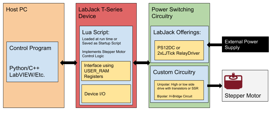
After understanding at a high level what needs to be accomplished, the basic work flow of: connecting to a device, configuring a device, and controlling a device can then be followed.
Connecting to a LabJack
The first step in the majority of LabJack applications is to open a connection to a device utilizing the LJM library. This is done utilizing the LJM_Open function which can be passed the device type, an identifier representing the serial number or IP address of the device, and the connection type to open a specific device. The open function can also be called with LJM_Open(LJM_dtANY, LJM_ctANY, LJM_idANY,...) and it will open any connected device. After opening the connection to the device, the open function will return a handle that can then be used to read from or write to the LabJack device for the body of the application. After the application body is finished, it is best practice to close the connection to the device using the LJM_Close function. For more on connecting to a LabJack device see LJM - Opening and Closing.
Configuring a LabJack for Stepper Motor Control
To configure a LabJack as a unipolar stepper motor controller, first load and run one of the LUA scripts, unipolar_full_step.lua or unipolar_half_step.lua (source code can be found Lua Script Examples section of our website), onto the LabJack and save the script as a power up default. For a guide on loading and saving a LUA script to a LabJack see the Standalone Lua Scripting Tutorial. The scripts can also be loaded in through an external program as can be seen in the python example found here and the LabVIEW examples discussed below. These lua scripts declare the FIO channels from the connection guide above and then define arrays that identify the order in which the coil end leads should be energized in order to successfully move the motor a desired number of steps in either full or half step mode. The LUA script then declares the following USER_RAM registers that can be modified by external programs in order to control the motor:
-
USER_RAM1_I32(46080): Target position (steps) -
USER_RAM2_I32(46082): Current position (steps) -
USER_RAM0_U16(46180): Enable (1 = enable, 0 = disable) -
USER_RAM1_U16(46181): eStop (1 = eStop, 0 = run) -
USER_RAM2_U16(46182): Hold Position (1 = Lock motor position, 0 = release motor after current move) -
USER_RAM3_U16(46183): Set Home (1 = sets current position as the 0 step position)
After understanding the basic scripts, advanced scripts can be developed that realize more advanced applications such as:
-
When using a rotational motor it is possible for position to be tracked by degrees.
-
If a stepper motor controls a linear slide, position can be tracked by distance.
-
Move a motor full-speed in a single direction.
Stepper Motor Control Psuedocode
After a stepper motor is properly connected and one of the configuration LUA scripts has been loaded to the LabJack, an external control application can read and write from the USER_RAM registers in order to monitor and control the operation. The pseudocode for basic motor control to move 200 steps can be seen below:
handle = ljm.openS("ANY,"ANY","ANY")
target_position = 200
ljm.eWriteAddress(handle,46183,0,1) //Signal to set home
ljm.eWriteAddress(handle,46182,0,0) //Do not hold motor for bench tests as it generates a lot of heat
ljm.eWriteAddress(handle,46080,2,target_position) //Write the new target position
ljm.eWriteAddress(handle,46180,0,1) //Enable motor movement
//Wait for motor to reach destination (enable will turn off automatically at destination)
waiting = true
while waiting:
waiting = ljm.eReadAddress(handle,46180,0) == 1
Example Application (Windows Only)
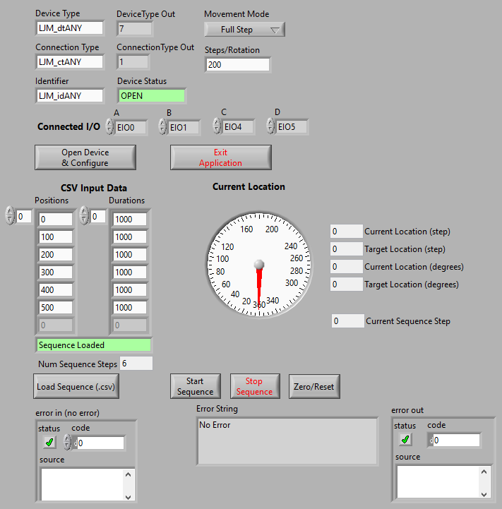
To make getting started with controlling stepper motors easier, we developed a LabVIEW application that downloads the correct .lua script to a T-Series device after editing the required I/O lines that need to be controlled and selecting between the full-step script as well as the half-step script. The application is available as a ".exe" (it is linked at the bottom of the page and here), and will run after downloading and installing our Windows LJM library and allowing it to install the LabVIEW 7.1 runtime engine. If a cross platform example is required, we also have a python example that can be downloaded and used which is published in the Lua Scripting Examples section of our website.
Connect to and Configure a device
Configure Device Parameters (DT, CT, ID): Configure Device Connection Parameters to determine what device gets opened.

-
Movement Mode and Steps/Rotation: Select either full or half step mode to decide which of the two LUA scripts is loaded to the device and define whether the motor will take full or half steps. Also, set the number of steps in one rotation so that the program can properly calculate the angular position of the motor.

Connected I/O: Select which I/O channels are connected to the stepper motor. The LabVIEW program will search for the lines of code in the LUA script file that declare the I/O channels and replace them with the channels specified in these controls before the LUA is loaded to the device.

Open Device & Configure: Connect to a device and configure it as a unipolar stepper motor controller. Pressing this button will force the program to try connecting to a device by the defined connection parameters and then configure the device with the defined movement mode and I/O lines.
Device Status: Verify that the device has been opened. If the device status field illuminates green and says "OPEN" the device has been opened and configured as a stepper motor controller.
Load and Start a Sequence of Steps

Load Sequence (.csv): Press this button and a prompt will appear to select a .csv file in the format:position1,duration1,position2,duration2,...Selecting a valid .csv will fill the Positions and Durations array.

Sequence Loaded: Verify that the sequence has been loaded. If the sequence status field illuminates green and says "Sequence Loaded" the .csv file has been read and loaded.
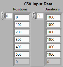
CSV Input Data: After loading a .csv file the data read in will appear in the CSV Input Data arrays. Before executing the sequence of moves in the arrays, the arrays can be modified by clicking inside the fields and altering the values.

Start and Stop Sequence: When Start Sequence is pressed, the stepper motor will navigate to each position in the Positions array and stay there for the corresponding duration in the Durations array. Stop Sequence will stop the motor after the current move is finished.

Zero/Reset: When this button is pressed, the motor will set its new home (0 steps) at its current position.
LabVIEW Examples Notice:
This example is the .exe of our stepper-motor-controller-app available to be downloaded on our LabVIEW for LJM webpage and utilizes the producer-consumer design pattern. A simpler example StepperController.vi as well as a more exhaustive example stepper-controller-with-reads.vi can be located in the folder:
LabVIEW_LJM/Examples/More/App-Notes/stepper-motor-control
The majority of a T-Series' device features can be used using the Write Read Loop with Config.vi. Assuming that one of the configuration LUA scripts has already been loaded to the LabJack, basic motor control can be done through this example using the registers specified above in "Configuring a LabJack for Stepper Motor Control". This example can be located in the folder:
LabVIEW_LJM/Examples/Basics
Further Reading & Research
-
A short article discussing the differences can be found in an article published by Portescap: "Unipolar Stepper Motor vs Bipolar Stepper Motors".
-
Article by Motion Control Tips: Open-loop stepper motor versus closed-loop stepper motor systems.
-
General video describing stepper motor basics: Stepper Motors with Arduino - Controlling Bipolar & Unipolar stepper motors
-
A video that has a good explanation of how to determine how to hook up each wire of a stepper motor: Stepper Motor Basics - 6 Wires Unipolar / Bipolar Motor. This explanation starts right at the beginning of the video.
-
A video that has good additional explanations of wavemode, full step mode, half step modes, and secondary explanations of microstepping: Electronic Basics #24: Stepper Motors and how to use them
-
A good video that animates the rotation & activation of stepper motor coils: Stepper Motor - How It Works.
