Overview
The U6 family of devices has the resolution and amplification necessary to directly measure thermocouples. By itself, a U6 can measure up to 4 thermocouples in a single-ended configuration. To handle more signals, LabJack has created the CB37 breakout board, which exposes more pins on the U6 and can measure up to 13 inputs in a single-ended configuration. However, this setup commonly leads to ground loops and is susceptible to noise. To fix this, we use a differential configuration. Using differential wiring, the U6 can measure 2 thermocouples, and with the CB37 breakout terminals, can support up to 6 thermocouples.
Please note that for accurate thermocouple measurements, you will need an external cold junction compensation (CJC) on one of the pins of the CB37.
If you would like to measure more than 7 thermocouples, we recommend upgrading to the T8.
Resolution
A type K thermocouple provides roughly 40 μV/°C. Output is -10.8 mV at -270 °C to +54.89 mV at 1372 °C.
As for the LabJack U6, here are the input resolutions for type K thermocouples:
|
ResolutionIndex |
Noise Free (°C) |
Effective (°C) |
|---|---|---|
|
8 |
0.2 °C |
0.04 °C |
|
12 |
0.03 °C |
0.005 °C |
In-depth breakdown: The maximum ResolutionIndex for a U6 is 8, and for a U6-Pro is 12, and the typical range used with thermocouples is ±100 mV. From Appendix B of the U6 User's Guide, looking at the ±0.1 range, the typical device resolution at ResolutionIndex=8 is about 6.3 μV noise-free and 1.3 μV effective (0.2 and 0.04 °C for a type K). At ResolutionIndex=12 it is about 1.2 μV noise-free and 0.2 μV effective (0.03 and 0.005 °C for a type K). The effective numbers mean that most samples (1 standard deviation) will fall in that range.
Note that the actual signal from a thermocouple will likely have real noise with it, beyond the internal noise of the device itself noted above. The high-resolution sigma-delta converter on the U6-Pro has excellent noise rejection, and in particular rejects 50/60 Hz noise when set to ResolutionIndex=12.
Also note that temperature in air tends to have lots of small fluctuations. What looks like noise on a thermocouple signal might be real temperature changes.
Accuracy
What's the difference between resolution and accuracy? See the Resolution and Accuracy app note.
From Appendix A of the U6 User's Guide, the device is calibrated to an absolute accuracy of ±0.01% full-span on the ±0.1 V range. Full-span is 0.2 V so that equates to an accuracy of ±20 μV, which corresponds to an accuracy of about ±0.5 °C for a type K thermocouple, which is more accurate than the thermocouple itself.
There are other sources of error in a thermocouple system, and in particular any error in cold junction temperature measurement is reflected as error in the thermocouple temperature. Expect about ±2.0 °C with the Internal Temperature Sensor, or about ±0.5 °C with the LM34CAZ temperature sensor. If the local ends of the thermocouples are all at the same temperature, then CJC error will affect them all equally and will not affect relative accuracy between the thermocouples.
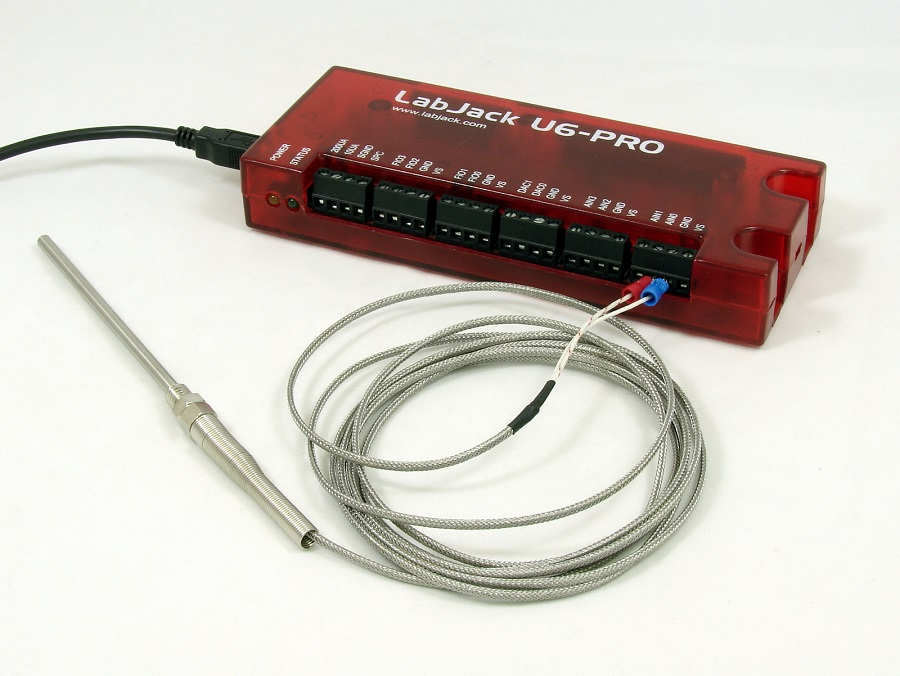
Tutorial: U6 and Type K Thermocouples
The following instructions will help you connect a Type K thermocouple to a LabJack U6 in a differential input configuration using LJControlPanel. After that has been done, there are instructions for how to read the value of a Type K thermocouple and log to file using LJLogUD.
1. Go through the U6 Quickstart Guide.
2. Wire the Thermocouple to the U6.
For this tutorial, we recommend configuring a differential connection between AIN0 and AIN1 on the U6.
You will need a 10-100 kΩ resistor, and a Type K Thermocouple. Connect as shown below:
-
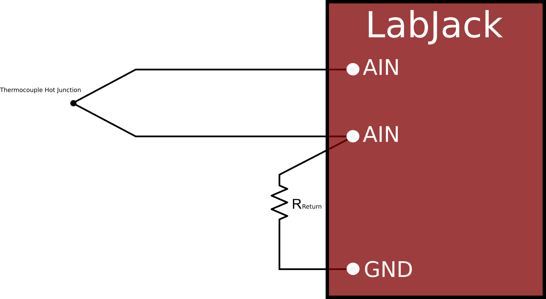
Thermocouple+ to AIN0.
-
Thermocouple- to AIN1.
-
100kΩ Resistor: AIN1 to GND.
-
Make sure all leads are securely clamped.
-
Have the remote end of the thermocouple in free air near the U6, not touching anything.
3. Run LJControlPanel, find and select the U6, and open the test panel.
You should see that Resolution is set to 0 (which is translated to an index of 8 on a normal U6 or an index of 9 on a U6-Pro). In the row for AIN0, check the Diff box to set AIN0 to differential, and change the Gain/Range to BI 0.1V. That means the ±0.1 V range which corresponds to a gain of x100 on the U6's internal amplifier.
4. Test Operation
Look at the voltage for AIN0, which is the differential reading AIN0-AIN1. With the remote end of the thermocouple in air near the U6, you should see a voltage close to 0.0., and it should have just a few microvolts of noise. The exact value you will see should be roughly -120 μV, indicating that the screw-terminals are a few degrees warmer than the ambient air, and thus the remote end of the thermocouple is a few degrees cooler than the cold junction (U6 screw terminals). If using the CB37 (discussed later), you will not see this as the CB37 does not have self-heating.
Now put your fingers on the remote end of the thermocouple to warm it up. You should see the voltage increase by roughly 40 μV per °C that the remote end is warmer than the U6 end.
5. Log Data with LJLogUD
If that all looks good, move on to our simple example program LJLogUD, which is an easy way to view and log data. We will use the first row to measure the cold junction temperature, so set +Ch=14 and -Ch=199 (single-ended). Channel 14 is the internal temperature sensor and returns degrees Kelvin on the U6, so if the U6 is at room temperature you should see ~298 in the Voltage column for row 0. To see degrees C or F change the scaling equation:
y=a // degrees K
y=a-273.15 // degrees C
y=(1.8*a)-459.67 // degrees F
Leave the range at BIP10V (bipolar 10 volts) for the internal temp sensor on row 0, but for all thermocouple rows set the range to BIPP1V (bipolar point 1 volt). That means the ±0.1 V range which corresponds to a gain of x100 on the U6's internal amplifier.
In the 2nd row, set +Ch=0 and -Ch=1, so we are taking a differential reading of the thermocouple voltage AIN0-AIN1. Set the range of this row to BIPP1V . You should see the same voltage and noise level that you saw earlier in LJControlPanel.
6. Apply Scaling Equations
Now lets change the scaling equation for row 1 (the 2nd row), so that instead of showing the raw thermocouple voltage it converts it to temperature. See the Scaling Equations description on the LJLogUD web page. The equation you want in this case is:
y=TCVoltsToTemp[K:b:a] // degrees K
y=TCVoltsToTemp[K:b:a]-273.15 // degrees C
y=1.8*(TCVoltsToTemp[K:b:a])-459.67 // degrees F
At this point you might notice that the thermocouple reading is low by a few degrees C. That is because the equation above is specifying a (raw value from row 0) as the cold junction temperature. That is the internal temp sensor, which is calibrated to report ambient temp, but the built-in screw-terminals on the U6 are typically a few degrees warmer than ambient. To account for this add a few degrees to the cold junction temp in the scaling equation:
y=TCVoltsToTemp[K:b:a+3] // degrees K
y=TCVoltsToTemp[K:b:a+3]-273.15 // degrees C
y=1.8*(TCVoltsToTemp[K:b:a+3])-459.67 // degrees F
If you added another differential thermocouple to AIN2/3 and set it up in the 3rd row, the scaling equation would have this form:
y=TCVoltsToTemp[K:c:a] //Type K, t/c voltage from 3rd row, CJ temp from 1st row
7. CB37 Setup
AIN0-AIN3 appear on the built-in screw-terminals of the U6, but to access all 14 analog inputs you need to use the DB37 connector. The CB37 terminal board is a handy way to access the DB37 connector, as it provides screw-terminal connections. Move the thermouple (or 2 thermocouples) from the terminals on the U6 to the same terminals on the CB37. Everything should keep working the same as the previous step, except that you should notice that the raw thermocouple voltages are closer to 0.000000 volts. This is because the CB37 screw terminals are now the cold junction, and they are the same temperature as air.
8. LM34 Setup
Now, for improved cold junction compensation, lets use an LM34CAZ on the CB37 for cold junction temperature, rather than the internal sensor on the U6. Bend the leads as needed and connect the LM34CAZ directly to AIN12/VS/GND on the CB37. Be careful about the sensor connection polarity, the diagram of the TO-92 package on the LM34 datasheet is showing the bottom view.
The screw-terminals on the CB37 are the cold junction for the thermocouples, so with the LM34 we are wanting to measure the actual temperature of the screw-terminals on the CB37. The CB37 does not warm up like the U6, so the screw-terminals on the CB37 will typically be at the same temperature as ambient air.
In row 0 (the first row) of LJLogUD, set +Ch=12 and -Ch=199. You can leave the range for this row at BIP10V, or if the LM34 temperature will stay below 100 °F you can use the BIP1V range. You should now see a voltage around 0.7 if the LM34 is at room temperature. Use the following scaling equations as desired:
y=100*a // EI-1034/LM34 voltage to °F
y=55.56*a - 17.78 // EI-1034/LM34 voltage to °C
y=55.56*a + 255.37 // EI-1034/LM34 voltage to °K
We now need to change all the scaling equations for the thermocouple rows. The last parameter in the TCVoltsToTemp function is cold junction temperature in °K. Since the raw value from the internal temp sensor was in °K, we simply used a in all the scaling equations, but now the raw value is in volts so we need to add scaling for the last parameter. The equation for the thermocouple connected to AIN0, which we put in row 1 (the 2nd row) of LJLogUD, would look like:
y=TCVoltsToTemp[K:b:(55.56*a)+255.37] //t/c voltage from 5th row, CJ temp from LM34 in 1st row