Overview
This page discusses the capabilities and usage of analog input features and characteristics specific to the T8.
For topics that apply to all devices such as: Common Uses, AIN Extended Features, Floating Inputs, Calibration, Volts vs Binary, Troubleshooting, and Accessories see: 14.0 Analog Inputs
Feature Highlights
|
Analog Inputs: |
8 (AIN0-AIN7) |
|
Voltage Ranges: |
±11 V, ±9.6 V, ±4.8 V, ±2.4 V, ±1.2 V, ±0.6 V, ±0.3 V, ±0.15 V, ±0.075 V, ±0.036 V, ±0.018 V
|
|
Resolution: |
24-bit |
|
Effective Resolution: |
15 to 22 bit
|
|
Max Data Rate: |
400000 samples/second (in stream mode (Appendix A-1) |
|
Sampling Modes: |
Simultaneous and differential |
|
Isolation: |
1000V |
Available AIN Channels
The LabJack T8 exposes:
-
All analog inputs on the screw terminals.
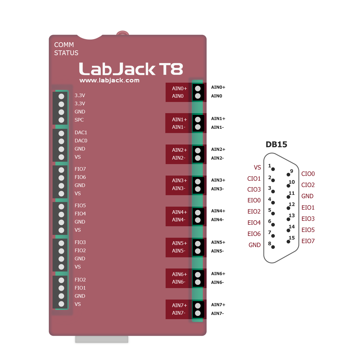
The LabJack T8 has 8 built-in analog inputs. All 8 analog inputs are individually isolated and are sampled simultaneously. The AINs can be read using register names AIN0-AIN7:
-
AIN0-AIN7: are available on the screw terminals and on the 2 pin OEM headers on each AIN. See "Duplicated Terminals" below.
-
Reading a Single AIN: Reading any of the AIN0-AIN7 registers will trigger a read of all AIN channels. The result from the requested channel will be returned immediately. The results from all of the analog inputs and temperature sensors will be saved in RAM. The stored results can then be read using the _CAPTURE registers. See the Simultaneous section below for more details.
-
Simultaneous Readings: To get simultaneous readings from multiple AIN and temperature registers, only the first channel should be read as AIN# or TEMPERATURE#. The remaining registers should be read using the appropriate _CAPTURE register. For example, to read the voltages connected to AIN0, AIN1, and AIN2, read the following list of registers:
[AIN0 (address 0), AIN1_CAPTURE (address 652), AIN2_CAPTURE (address 654)]
See more information about the TEMPERATURE# registers in the Internal Temp Sensor section. -
Sequential Readings: If multiple AIN# registers are read in one command rather than using the _CAPTURE registers, each AIN reading will be acquired sequentially rather than simultaneously, and each reading will take 0 to 1/AIN_SAMPLING_RATE_HZ seconds to be acquired. See the AIN Sampling Rate section below for further sampling information.
Isolation
The T8 features eight individually isolated analog inputs (AINs). Each channel is galvanically isolated from the T8's main ground and from the ground of all other AINs. This isolation provides some significant benefits:
-
Elimination of Ground Loops: By preventing current flow between AIN grounds, isolation eliminates unintended ground paths that can introduce noise and offsets. For a detailed explanation of ground loops, refer to: Ground Loops
-
High Common-Mode Voltage Tolerance: Isolation allows each AIN to accurately measure voltages despite large differences in common-mode voltage. For example, AIN0 can measure a 5V signal referenced to earth ground, while AIN1 simultaneously measures a 5V signal at 240V relative to earth ground.
Simultaneous
The T8's analog inputs are synchronously sampled using a shared clock. This ensures all analog-to-digital conversions begin and end simultaneously. Simultaneous sampling confers a few benefits:
-
Elimination of Time Skew: Unlike multiplexed systems that sample channels sequentially, simultaneous sampling captures all channels at the exact same instant. This eliminates time skew, which is crucial for accurately analyzing phase relationships and transient events.
-
Precise Phase Measurements: In applications like power analysis, vibration analysis, and control systems, accurate phase measurements are essential. Simultaneous sampling ensures that these measurements are reliable.
-
Reduced Settling Errors: Each channel has its own dedicated ADC, allowing for the full sampling rate to be achieved on all channels simultaneously.
The analog inputs can be read simultaneously or sequentially. The sampling mode is controlled through register selection and communication mode. When using command-response, a read request to any AIN# register initiates a simultaneous analog-to-digital conversion across all analog input channels. All of the results produced are stored in RAM. The result from the requested AIN# is returned as the response to the read request. The captured values can then be accessed through the corresponding AIN#_CAPTURE registers. For continuous data acquisition using stream mode, refer to the Streaming AIN section.
Resolution
The resolution of the T8’s analog inputs can be adjusted. All analog inputs share a single resolution index. Writing to any of the resolution index registers will set the resolution for all channels.
Higher resolution indices reduce noise and increase effective resolution, but are constrained by achievable sampling rates. Rate limits for each resolution index can be found in the tables here: A-3-3-2 T8 Noise and Resolution
When the resolution index is set to zero, the device will select the best resolution for the situation. The best resolution will depend on the sampling rate. Check the register descriptions below for details.
These registers set the Analog Input resolution for command-response readings. For stream, refer to the "Streaming AIN" section below.
Range (Gain)
The input range of the T8’s analog inputs is adjustable, with smaller ranges providing higher resolution and accuracy. Refer to section A-3-3-2 for detailed resolution information at various ranges.
Each analog input channel has an independent range setting. The setting can be modified when stream mode is inactive. The following registers control the T8's analog input ranges:"
These registers set the Analog Input ranges for command-response and stream.
Sampling Rate
The T8's analog inputs (AINs) operate continuously. They must run continuously in order to maintain synchronization. The rate of the conversions is controlled by the AIN_SAMPLING_RATE_HZ register.
Due to the inherent limitations of digital systems, the actual sampling rate may deviate slightly from the requested rate. The actual rate can be obtained from the AIN_SAMPLING_RATE_ACTUAL_HZ register after setting the desired rate in AIN_SAMPLING_RATE_HZ. For example, setting AIN_SAMPLING_RATE_HZ to 100 might result in AIN_SAMPLING_RATE_ACTUAL_HZ reading 100.058.
The sampling time is affected by the sampling rate. When a new reading is requested, the T8 returns the result of the next completed conversion. Consequently, the latency for a new reading ranges from zero to the sampling period. For instance, at a 100 Hz sampling rate, the latency will be between 0 and 10 milliseconds.
The acquisition time is controlled by the sampling rate and the resolution index. This is true for both stream and command-response modes. See the below list to calculate acquisition time:
-
Resolution index 3-16: Acquisition time is 1 over the sampling rate. Tacq = 1 / sampling_rate
-
Resolution index 1-2: Acquisition time is 1 over two times the sampling rate: Tacq = 1 / (2 * sampling_rate)
These registers set the sampling rate for command-response readings. For stream, refer to the "Streaming AIN" section below.
Settling
The T8 features individual AIN chains for each analog input. Settling is only required after changing the configuration of the analog inputs and is usually complete after 2-3 sample times.
Streaming Analog Inputs
Stream allows for automatic and high-speed data collection. See 3.2 Stream Mode for details. Some stream configurations override the normal AIN configurations:
-
Use STREAM_SCANRATE_HZ instead of AIN_SAMPLING_RATE_HZ
-
Use STREAM_RESOLUTION_INDEX instead of AIN_RESOLUTION_INDEX.
Command-Response while Streaming
Command-response operations can be performed while a stream is active. Commands sent while stream is running will take longer to execute than normal. The magnitude of the slowdown increases with stream rate.
The stream scan clock is generated by the analog input system. Stream always needs exclusive control of the analog input system. Analog inputs can not be read by C-R while stream is running.
For more information about stream see: 3.2 Stream Mode
Operation
The analog input system performs several functions, each requires several steps:
-
Apply analog input settings: Any time a setting such as range, rate, or resolution is changed, the analog input system will stop all AIN operations, configure the circuitry for the new settings, then restart the AINs. The whole process takes about 40 milliseconds.
-
Collecting Samples in command-response mode: Each time a new result is requested from the AIN# registers, the analog inputs system will wait for a new result to be completed. That means that the time needed to get a new reading can be anywhere from nearly instant to as long as one sample period. For additional details see the Simultaneous section above.
-
Collecting Samples in stream mode: While stream is active, the same clock that is used to control the ADCs is used as the stream scan timer. The result is exactly one stream scan each time the converters complete a result. This both ensures synchronization and limits the number of times the AINs can be read in a scan one. See the Stream documentation for more details: 3.2 Stream Mode
-
Switching between stream and command-response configuration sets: When stream is started, the AIN system will be reconfigured to the stream settings. That process is the same as described in “Apply analog input settings“ above and takes ~40 milliseconds which adds time to the stream startup. When stream is stopped, the AIN system will be reconfigured to the command-response settings. The 40 milliseconds will be added to the stream stop operations.
Examples