Overview
This page discusses the capabilities and usage of the analog input features and characteristics specific to the T7.
For topics that apply to all devices such as: Common Uses, AIN Extended Features, Floating Inputs, Calibration, Volts vs Binary, Troubleshooting, and Accessories see: 14.0 Analog Inputs [T-Series Datasheet]
Feature Highlights
|
Analog Inputs: |
14 (AIN0-AIN13) |
|
Voltage Ranges: |
±10 V, ±1 V, ±0.1 V, ±0.01 V (Appendix A-3-2-3) |
|
Resolution: |
T7: 16-bit
|
|
Effective Resolution: |
T7: 16 to 19 bit*
|
|
Max Data Rate: |
100000 samples/second in stream mode (Appendix A-1) |
|
Sampling Modes: |
Configurable as single-ended or differential |
|
Extended Channels: |
The number of analog inputs can be extended to 84 with a MUX80 (AIN48-AIN127) |
|
Instrumentation Amplifier: |
The T7’s analog inputs are connected to a high-impedance instrumentation amplifier, as shown in Figure 4.2-2. |
Available AIN Channels
Each T7 has 14 analog inputs with the possibility of expanding to even more:
-
Some AINs on the screw terminals (AIN0-AIN3).
The LabJack T7 has 14 built-in analog inputs, readable as AIN0-13:
-
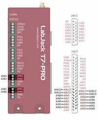
AIN0-AIN3 are available on the screw terminals and on the DB37 connector. See "Duplicated Terminals" below.
-
AIN4-AIN13 are available only on the DB37 connector.
The voltage on an analog input can be measured by reading form the below registers.
In addition to the 14 built-in analog inputs, the T7 has special and extended channels.
-
AIN14 is internally connected to an internal temperature sensor.
-
AIN15 is internally connected to GND. Useful for measuring noise or looking at offset error.
-
AIN16-AIN127 are Extended channels. Using these channels requires external multiplexing hardware. See the Extended Channels section for more details.
Resolution
The T7 can adjust the resolution of its analog inputs.
A higher resolution index results in lower noise and higher effective resolution at the expense of increased sampling times.
In command-response mode, each channel has its own resolution setting. In stream mode, all channels must use the same resolution.
When the resolution index is set to zero, the device will select the best resolution for the situation. The best resolution will depend on the operating mode and sampling rate. Check the register descriptions below for details.
These registers set the Analog Input resolution for command-response readings. For stream, refer to the "Streaming AIN" section below.
Range (Gain)
The T7 can adjust the input range of its analog inputs. Smaller ranges produce higher resolution measurements. For more information about resolution at different ranges see A-3-2-2.
Each analog input has its own independent range setting and the ranges can be changed as long as stream is not running. The below registers can be used to control the range of the T7’s analog inputs.
These registers set the ranges for command-response and stream.
Single-ended or Differential
Single-ended AIN readings are read with ground (GND) as a reference point. Differential readings use a second AIN as a reference point. For more information about differential readings, see Differential Readings
For AIN0 through AIN13, differential channels are adjacent even/odd pairs such that the positive channel is even and the negative channel is greater than the positive channel by 1. Odd channels, such as AIN3_NEGATIVE_CH (address 41003), should not be written to because only an even channel can have an associated negative channel.
The analog inputs can be configured as single-ended or differential by writing to the AIN#(0:13)_NEGATIVE_CH or AIN_ALL_NEGATIVE_CH registers.
When reading differential AINs, the positive AIN's configurations are used and the negative AIN's configurations are ignored. For example: when reading AIN0 with AIN0_NEGATIVE_CH is set to 1, the T7 will measure AIN0-AIN1 using the settings for AIN0 (such as AIN0_RESOLUTION_INDEX, and AIN0_RANGE).
Note that single-ended and differential are not the same as bipolar and unipolar. The T7’s inputs are always bipolar.
These registers set the differential configuration for command-response and stream.
Settling
The settling registers control the time from a step change in the input signal to when the signal is sampled by the ADC. A step change in this case is caused when the internal multiplexers change from one channel to another. In general, more settling time is required as gain and resolution or source impedance are increased.
The value 0 sets automatic settling, which is recommended for most applications. This "auto" settling ensures that the device meets specifications at any gain and resolution for source impedance up to at least 1000 ohms.
Normally, very little settling is required because once a channel has been selected, inputs are connected to a high-impedance instrumentation amplifier, as shown in Figure 4.2-2.
For a more in depth discussion of settling see: Analog Input Settling Time
These registers set the settling time for command-response readings. For stream, refer to the "Streaming AIN" section below.
Power
The T7 can shut down most of its analog input system. This will save ~30 mA, see Table A5-6 for power consumption in different operating states.
When the T7’s analog inputs are disabled, the input multiplexors remain powered. This prevents the AIN system from drawing current from any connected signals.
The following registers control the power state of the T7’s analog inputs.
Streaming AIN
Stream allows for automatic and high-speed data collection. See 3.2 Stream Mode for details. Some stream configurations override the normal AIN configurations:
-
Use STREAM_SETTLING_US instead of AIN_SETTLING_US.
-
Use STREAM_RESOLUTION_INDEX instead of AIN_RESOLUTION_INDEX.
Command-Response while Streaming
Command-response can be performed while a stream is active. Commands sent while stream is running will take longer to execute than normal. The magnitude of the slowdown increases with stream rate.
If any of the channels in the scan list are analog inputs, then streaming needs exclusive control of the analog input system. The result is that analog inputs (including the internal temperature sensor) cannot be read via command-response while a stream is active.
If the stream scan list does not contain any analog inputs, then the AIN system is free to be used by command-response.
For more information about stream see: 3.2 Stream Mode
Duplicated Terminals (AIN0-AIN3)
AIN0-AIN3 appear on the built-in screw-terminals and also on the DB37 connector. Users should only connect to one or the other, not both at the same time.
To prevent damage due to accidental short circuit, both connection paths have their own series resistor. All AIN lines have a 2.2k series resistor, and in the case of AIN0-AIN3 the duplicated connections each have their own series resistor, so if you measure the resistance between the duplicate terminals you will see about 4.4k.
Operation
The T7’s analog input system consists of multiplexors, an instrumentation amplifier with programmable gains, and one or two ADCs. Those components work together to select and measure the T7's analog inputs. The following is the sequence used measure a single AIN:
-
Set the multiplexors according to the requested AIN#. This also configures the reading to be the single ended or differential according to the AIN#_NEGATIVE_CH register.
-
Set the amplifier according to the range setting selected by AIN#_RANGE
-
Wait for settling. At this point the multiplexors have selected the desired channel and the system has started to settle. The signal to charge up the input capacitance, which is ~300 pF. And the amplifier needs time to settle. The settling time is controlled with the AIN#_SETTLING_US register. If the specified time is zero, 0, the settling time will be selected based on the selected range and resolution.
-
Read binary samples from the converter. Higher AIN#_RESOLUTION_INDEX settings require more samples to be taken.
-
Calculate the final binary result from the list of results from step 4.
Examples: