T-series devices have the capability to read and interpret a quadrature input signal as a part of the Digital I/O Extended Feature (DIO-EF) system. In this example we will use the Kipling Register Matrix to enable and read a quadrature encoder. The quadrature input mode will immediately begin storing the encoder count in a register once enabled and this register can be read or cleared at the user's convenience.
This example uses FIO0 and FIO1 (aka DIO0 and DIO1) which are easily accessible on the T7 and T8 as the respective phase A and phase B of the encoder. For the T4, use FIO4 and FIO5 (DIO4 and DIO5) instead. For more on the specifics of quadrature input see Quadrature In [T-Series Datasheet].
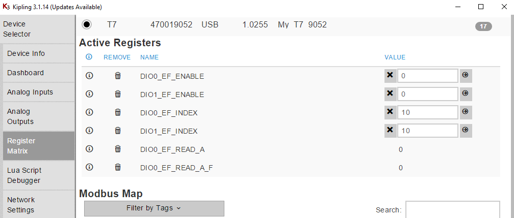
1. Go to the Register Matrix in Kipling and type "dio0" in the search box to narrow the list of registers. Add the _ENABLE, _INDEX, _READ_A, and _READ_A_F registers to the active list as shown. Then type "dio1" in the search box and add the enable and index registers to the active list as shown.

2. Write the following configuration values in this order. NOTE: The enable registers must be set to zero while setting the index registers.
DIO0_EF_ENABLE = 0 // Cannot change index if enabled.
DIO1_EF_ENABLE = 0 // Cannot change index if enabled.
DIO0_EF_INDEX = 10// Set to quadrature input extended feature
DIO1_EF_INDEX = 10 // Set to quadrature input extended feature
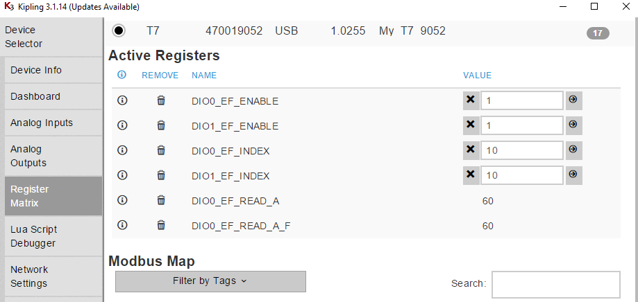
DIO0_EF_ENABLE = 1 // Enable and start quadrature input
DIO1_EF_ENABLE = 1 // Enable and start quadrature input
3. After writing the necessary configuration values from step 2 to their respective registers, quadrature input should be enabled on DIO0 and DIO1 and the DIO0_EF_READ_A and DIO0_EF_READ_A_F registers should display the current quadrature encoder count in two's complement and float form respectively. To test this, try turning the encoder slightly and see if these values change.
4. To save the configuration, so the counter will be configured at boot-up, go to the Power-Up Defaults tab, make sure the Current Device Settings option is selected, and click Configure Power-up Defaults. This is suggested if using LJLogM, LJStreamM, or other simple polling programs, but not needed if your software will do the configuration.
More on _EF_READ_A and _EF_READ_A_F Registers
The DIO0_EF_READ_A_F register will display the encoder counts as a positive integer if the encoder is turned clockwise from its initial position and will display the counts as a negative integer if the encoder is turned counterclockwise. The DIO0_EF_READ_A register will display the encoder counts as a positive integer just like the DIO0_EF_READ_A_F register when the encoder is turned clockwise. However, when the encoder is turned counterclockwise, the DIO0_EF_READ_A register will display a large positive integer representing the two's complement conversion of the encoder count. WARNING: The 32 bit DIO0_EF_READ_A_F float register begins losing precision once values become too high (~greater than 2^23-1). Because the DIO0_EF_READ_A_F register is only accurate within this range, users who intend to create an application that will involve very large encoder counts outside of this range can simply poll the DIO0_EF_READ_A register and then use a 2's complement conversion to convert counterclockwise encoder movement to a more easily interpreted negative integer. A two's complement negative number will have a one as the most significant bit, and to convert it into a negative integer simply invert all of the bits in the two's complement and then add one to the resulting number. Finally, multiply the result by negative one to get the negative integer representation.
Troubleshooting
1. If no counts are being read in from the encoder whatsoever, a simple troubleshooting technique is to plug a wire into a GND terminal of the LabJack and then tapping the other end randomly in the inside back of both of the quadrature inputs (DIO0 and DIO1). This should induce at least a single count to ensure that the quadrature inputs are indeed configured correctly.
2. Another option for troubleshooting if no counts are being read from the encoder is to connect the two phases of the encoder to a scope and then connecting the GND and VCC connections of the encoder to a LabJack. When the encoder is turned, the scope should depict two out of phase square waves as discussed here. If the expected square waves do not appear on the scope then there is an issue with the encoder itself.
3. A third way to test if the encoder itself is running properly is to connect the two phases to DIO0 and DIO1 and connecting the VCC and GND of the encoder to their necessary terminals on the LabJack and then connecting to the device in Kipling. Then, open the Dashboard tab within Kipling and make sure that FIO0 and FIO1 are set to input mode. When the encoder is turned, FIO0 and FIO1 should intermittently switch between HIGH and LOW, mimicking the square wave behavior expected to be seen in troubleshooting tip 2 above.
4. Another debugging technique would be to enable a counter on a DIO terminal and connecting one of the quadrature inputs to the terminal. As the counter will count the number of rising edges of a signal, if the encoder is working properly this count should increase when the encoder is turned.
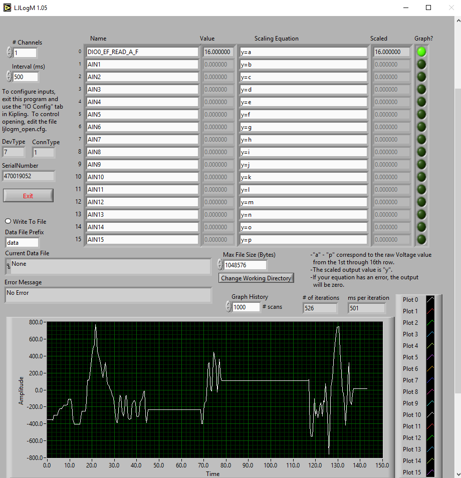
Reading the Encoder Count in LJLogM
Once the encoder is configured and the configuration is saved as a power-up default (above), you can read DIO0_EF_READ_A or DIO0_EF_READ_A_F using any row in LJLogM. If the encoder is turned clockwise or counterclockwise, the graph should display a curve that dynamically mirrors the encoder count.
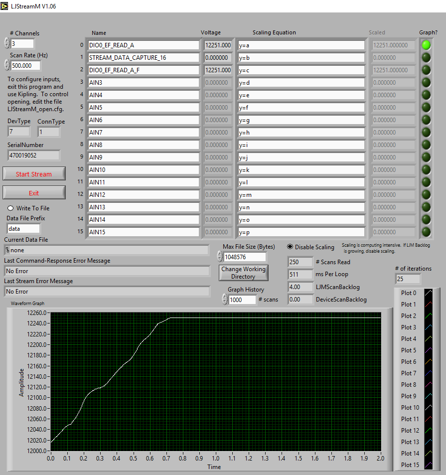
Reading the Encoder Count in LJStreamM
Once the LabJack is configured for quadrature input and this configuration is saved as a power up default (above), you can read DIO0_EF_READ_A using any row in LJStreamM. When not streaming, LJStreamUD is grabbing reads in command-response mode which is able to read the entire 32-bit value, but in stream mode DIO0_EF_READ_A only returns the lower 16-bits so if you want the upper 16-bits you need to also read STREAM_DATA_CAPTURE_16, which is mentioned on the LJLog/Stream Scaling Equations page.
Using a Quadrature Encoder in Your Program
To configure the counter you can use steps 1-4 above or write DIO0_EF_ENABLE = 0, DIO1_EF_ENABLE = 0, DIO0_EF_INDEX = 10, DIO1_EF_INDEX = 10, DIO0_EF_ENABLE = 1 and DIO1_EF_ENABLE = 1 in your program. You can do the latter with a couple calls to eWriteName or a single call to eWriteNames.
To read the encoder count value you need to read DIO0_EF_READ_A or DIO0_EF_READ_A_F. You can do this with a call to eReadName. If using stream mode you also need to read STREAM_DATA_CAPTURE_16 if you want the upper 16-bits.
In the applicable LJM example archive, look for an example called "Write Read Loop with Config" that can be used to configure and read the counter.
For more on quadrature encoders, see the Quadrature In [T-Series Datasheet], our rotary encoder app note, or one of our example LabVIEW quadrature applications in the LJM LabVIEW archive.