Overview
T7 devices have the resolution and amplification necessary to directly measure thermocouples. Through only the built-in screw terminals, a T7 can measure up to 4 single-ended thermocouples. Beyond that, add a CB37 to handle up to 6 (recommended max) differential thermocouples, or add a Mux80 to handle up to 26 (recommended max) differential thermocouples. For more details see Selecting the Right Hardware.
Please note that for the best accuracy, we suggest adding a cold junction sensor on one of the pins of the CB37.
Resolution
A type K thermocouple provides roughly 40 μV/°C. Output is -10.8 mV at -270 °C to +54.89 mV at 1372 °C. Based on that, we calculate the following resolutions for the T7 or T7-Pro:
|
ResolutionIndex |
Noise Free (°C) |
Effective (°C) |
|---|---|---|
|
8 |
0.2 °C |
0.04 °C |
|
12 (T7-Pro) |
0.03 °C |
0.005 °C |
In-depth breakdown: The maximum ResolutionIndex for a T7 is 8, and for a T7-Pro is 12, and the typical range used with thermocouples is ±100 mV. From Appendix A-3-1 of the T7 User's Guide, looking at the ±0.1 range, the typical device resolution at ResolutionIndex=8 is about 6.3 μV noise-free and 1.3 μV effective (0.2 and 0.04 °C for a type K). At ResolutionIndex=12 it is about 1.2 μV noise-free and 0.2 μV effective (0.03 and 0.005 °C for a type K). The effective numbers mean that most samples (1 standard deviation) will fall in that range.
Note that the actual signal from a thermocouple will likely have real noise with it, beyond the internal noise of the device itself which is included above. The 24-bit low-speed sigma-delta converter on the T7-Pro has excellent noise rejection, and in particular rejects troublesome 50/60 Hz noise when set to ResolutionIndex=12.
Also note that temperature in air tends to have many small fluctuations. What looks like noise on a thermocouple signal might be real temperature changes.
Accuracy
What's the difference between resolution and accuracy? See the Resolution and Accuracy app note.
From Appendix A-3 of the T7 User's Guide, the device is calibrated to an absolute accuracy of ±0.01% full-span on the ±0.1 V range. Full-span is 0.2 V so that equates to an accuracy of ±20 μV, which corresponds to an accuracy of about ±0.5 °C for a type K thermocouple, which is more accurate than the thermocouple itself.
There are many other sources of error in a thermocouple system, and in particular, any error in cold junction temperature measurement is reflected as error in the thermocouple temperature. Expect about ±2.0 °C with the Internal Temperature Sensor, or about ±0.5 °C with the LM34CAZ temperature sensor.
When you are using multiple probes, if all thermocouple cold junctions are at the same temperature, errors in cold junction compensation will be uniform, not affecting the relative accuracy between the thermocouples.
Tutorial: T7 and Type K Thermocouples
The following instructions will help you connect a Type K thermocouple to a LabJack T7 in a differential input configuration using Kipling. After that has been done, there are instructions for how to read the value of a Type K thermocouple and save the data to a .csv file using LJLogM.
1. Go through the T7 Quickstart Guide.
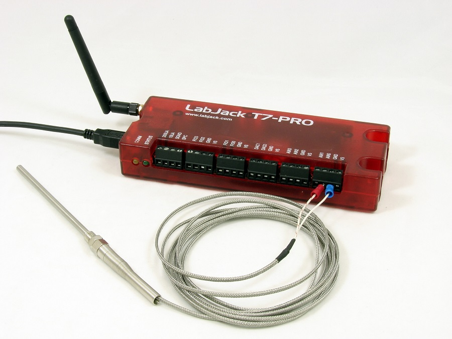
2. Wire a thermocouple to the T7.
Thermocouples are notoriously difficult to use, so it is best to start by having success with the simplest setup possible. Connect a single Type K to the built-in screw terminals of the T7, using a single-ended connection, and have no other connection to the T7 besides power/comm. The remote end of the thermocouple should be in free air near the T7, and not touching anything besides air. Pull on both thermocouple leads to make sure both are securely clamped in the screw terminal.
-
Thermocouple + to AIN0
-
Thermocouple - to GND
3. Run our Kipling software and connect to the T7.
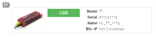
Plug the device in over USB, and then click Refresh Devices in Kipling. Click the Green USB button to open the T7.
4. Configure the analog input in Kipling.
There are various ways to do configuration, but this tutorial uses the wizard in Kipling. Go to the Analog Inputs tab, press the + button for AIN0, and set Extended Feature (EF) to TypeK Thermocouple.
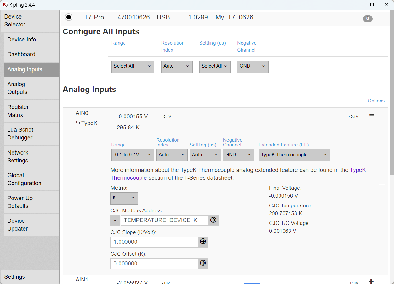
The thermocouple voltage in the above screenshot is about -160 μV. Since the response of a type K is about 40 μV/K, this reading tells us that the remote end of the thermocouple is about 4 degrees cooler than the local end (T7 screw terminals), which makes sense for a warmed up T7.
The calculated thermocouple temperature is 295.8 K. This makes sense since the CJC (local end) temperature is 299.7 K and the -160 μV reading tells us the remote end is 4 degrees cooler than the local end.
5. Save the device settings.
Go to the Power-Up Defaults tab of Kipling and click Configure Power-up Defaults. This saves the current devices settings so they will now be the settings after power-up.
6. Use an LM34 for CJC.
Any error in cold junction measurement will show up in the calculated thermocouple temperature, so applications going for the best accuracy might use an external cold junction sensor. For example, when connecting thermocouples to a CB37 terminal board, the CB37 screw terminals are the cold junction so it is common to put an LM34CAZ sensor in AIN12 on the CB37, and then set the following in Kipling:
-
Set
CJC Modbus AddresstoExternal Sensor on AIN12. -
Set
CJC Slopeto 55.56. -
Set
CJC Offsetto 255.37.
7. Use a differential connection.
Often a differential connection is desirable for thermocouples. To change to differential set Negative Channel to AIN1 and make the wiring as follows:
-
Thermocouple + to AIN0
-
Thermocouple - to AIN1
-
100kΩ Resistor: AIN1 to GND
8. Log Data with LJLogM
There are various software options, but LJLogM is a simple example application for Windows that lets you log data to file. Once the AIN extended feature is configured (above), you can read AIN0_EF_READ_A using any row in LJLogM.
Close the connection in Kipling before opening LJLogM. A LabJack can only be opened via USB by one software process.
Going Further
The T7 is compatible with multiple thermocouple types including B, C, E, J, K, N, R, T, and S. For an up-to-date list, look at section 14.1.1 Thermocouple which is in the AIN/AIN_EF section of the T-Series Datasheet.
Multiple Thermocouples (2 to 42)
The T7 is capable of measuring up to 42 thermocouples using differential measurement techniques when combined with a Mux80 and any necessary CB37 expansion boards. When connecting more than one thermocouple at a time it is recommended that customers connect them so that differential input analog measurements can be made. For example, connect the positive lead of the thermocouple to a positive analog input channel and then the negative lead of the thermocouple to a negative analog input channel. Then connect a resistor (somewhere between a 10KΩ and 1MΩ in value) between the negative lead and an available GND terminal. Collecting data from multiple thermocouples using the differential input mode helps address several of the common thermocouple complications, for more details see the "Thermocouple Complications" section in the general thermocouples app-note, specifically ground loops.
For more information about which channels are positive and negative, look at the "Single-ended or Differential" section of the T-Series Analog Inputs datasheet page. Also look at Table 2 in the Mux80 datasheet for channel-mapping/wiring details regarding positive and negative channels as well as the extended channels section in the T-Series devices datasheet.
To configure analog inputs beyond AIN0-AIN13, you can use the Register Matrix in Kipling, do it programmatically using one of our LJM wrappers, or on Windows you can use "AINEFConfigTool.exe" from the Additional Utility Applications page. This tool is useful any time you want to configure the same AIN_EF settings for many channels.
Thermocouples in Custom Applications
Go through the above tutorial first, and then to configure and read thermocouples in your own code refer to the AIN-EF documentation and thermocouple code examples.
Most custom applications will have code at the beginning to do all needed configuration (e.g. AIN_EF settings). Often such a program would also write IO_CONFIG_SET_DEFAULT_TO_CURRENT = 1 to save the configuration as the boot-up default, in case the device reboots (e.g. power cycle) while the program is running.
Thermocouples in Stream Mode
The AIN_EF functionality is not compatible with stream mode acquisition. Stream mode is for high-speed acquisition, which would be unusual with thermocouples, but this can be handled as follows:
-
Configure analog inputs as needed. Range is typically set to ±0.01 and negative channels might need to be set to specify differential readings.
-
Do normal analog input readings (e.g. AIN0) to get the raw thermocouple voltages and perhaps a cold junction sensor voltage.
-
Use the TCVoltsToTemp function in your software to handle the voltage to temperature conversion on the host computer.