T-series devices have various timers as part of the Digital I/O Extended Feature (DIO-EF) system. In this example we will use the Kipling Register Matrix to configure and read a timer in the Frequency In mode. This feature will measure the period/frequency of a digital input signal by counting the number of clock source ticks between two edges: rising-to-rising (INDEX=3) or falling-to-falling (INDEX=4). For this example we use clock 0 with default settings.
This example uses FIO0 (aka DIO0) which is handy on the T7 and T8. For the T4 use FIO4 (DIO4) instead.
1. Go to the Register Matrix in Kipling and type "clock0" in the search box to narrow the list of registers. Add the clock0 enable register to the active list. Change the search term to "dio0" and add the INDEX, ENABLE, READ_A_F, and READ_B_F registers to the active list.
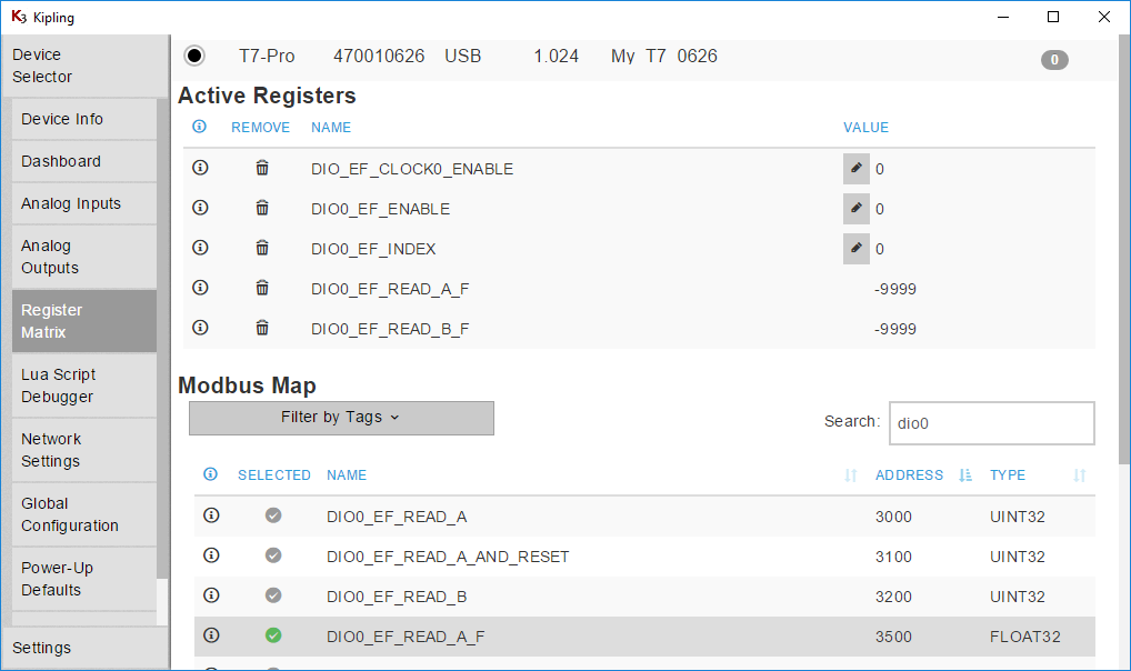
2. Change the search term to "dac1" and add DAC1_FREQUENCY_OUT_ENABLE to the active list. Writing 1 to this register enables a 10 Hz square wave output on the DAC1 terminal (T7 requires firmware 1.0234+).
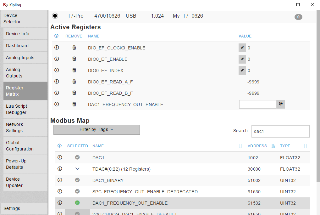
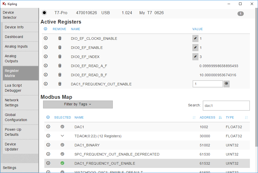
3. Write the following values:
DIO_EF_CLOCK0_ENABLE = 1 // Enable clock0. Default frequency is 80 MHz.
DIO0_EF_ENABLE = 0 // Cannot change index if enabled
DIO0_EF_INDEX = 3
DIO0_EF_ENABLE = 1
DAC1_FREQUENCY_OUT_ENABLE = 1
INDEX=3 times between rising edges while INDEX=4 times between falling edges.
4. The FIO0 line should now be measuring the time between rising edges. The period in seconds is returned by DIO0_EF_READ_A_F and the frequency in Hz is returned by DIO0_EF_READ_B_F. Connect a jumper from DAC1 to FIO0 and DIO0_EF_READ_A_F should read about 0.1 and DIO0_EF_READ_B_F should read about 10. Note that the register DIO0_EF_READ_B_F is a capture register, and thus it is only updated whenever the DIO0_EF_READ_A register is read.
Kipling 3.1.10 has an issue where dio-ef read registers may not initially update. To work around this, change to a different tab (e.g. Analog Outputs), then change back to the Register Matrix tab.
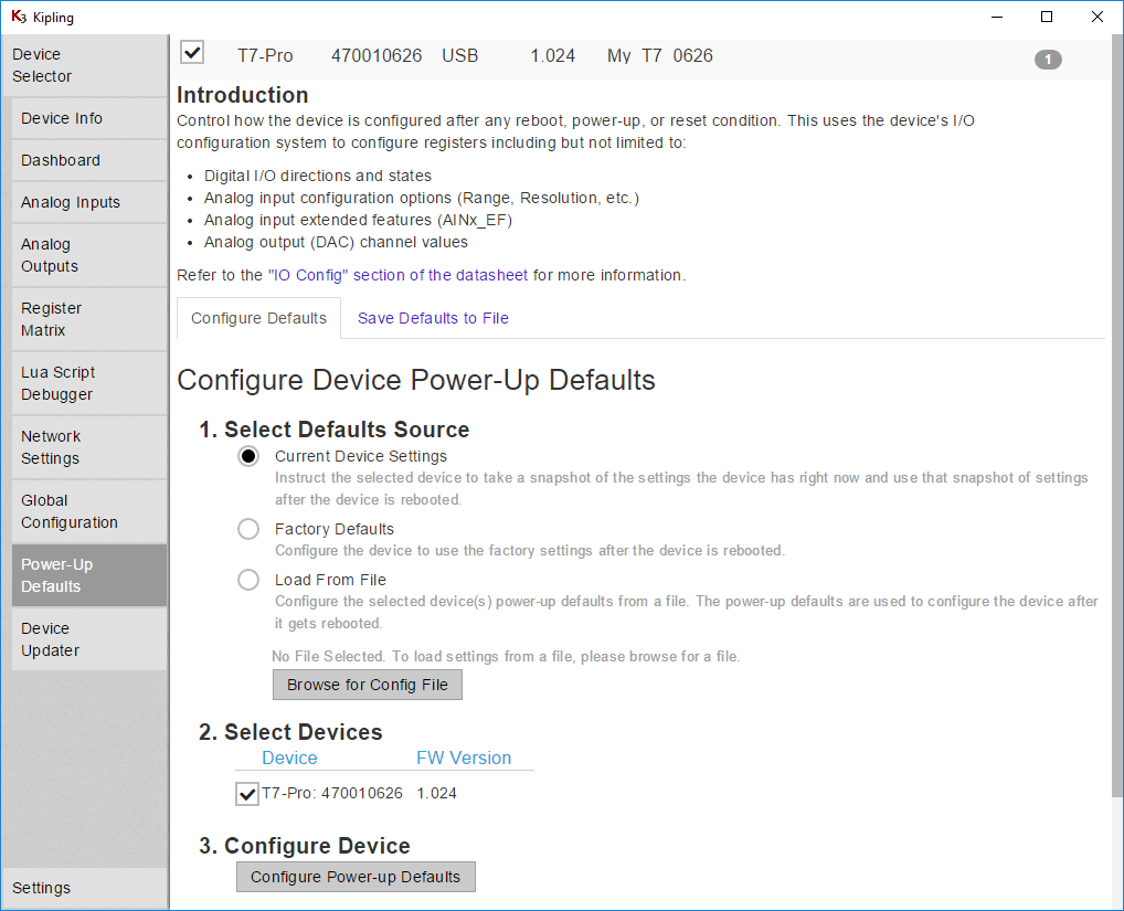
5. To save the configuration, so the frequency measurement will be configured at boot-up, go to the Power-Up Defaults tab, make sure the Current Device Settings option is selected, and click Configure Power-up Defaults. This is suggested if using LJLogM, LJStreamM, or other simple polling programs, but not needed if your software will do the configuration.
Troubleshooting
-
T7: Firmware 1.0234 or higher is required for the 10 Hz test signal enabled by writing
DAC1_FREQUENCY_OUT_ENABLE = 1. -
Touching a conductor to the top of the screw head of an un-clamped screw terminal is rarely a valid connection. The screw head is usually valid when the terminal is clamped, but the only guaranteed valid connection is to securely clamp a conductor inside the screw terminal.
-
This example assumes default clock settings. Non-default clock settings might cause problems. Try using these clock settings:
DIO_EF_CLOCK0_DIVISOR = 1
DIO_EF_CLOCK0_OPTIONS = 0
DIO_EF_CLOCK0_ROLL_VALUE = 0
DIO_EF_CLOCK1_ENABLE = 0
DIO_EF_CLOCK2_ENABLE = 0 -
Consider taking a step back to the counter tutorial. A counter is a little simpler than this frequency measurement timer.
Connecting your Signal to a Frequency Input
The typical connection would be +signal to FIO0 and -signal to GND, but the exact connections can depend on the details of your signal. Likely resources are the Driven Signals and Open-Collector Signals app notes.
The digital input in this example is looking for a rising edge, which means that the state of the digital input changes from low to high. On T-series devices a low is less than 0.5 volts and a high is greater than 2.64 volts (see specs in appendix of device datasheet for details).
No measured value or measured value too low: This problem suggests that the voltage from DIOx versus GND is not changing from <0.5 volts to >2.64 volts. Use a DMM or oscilloscope connected to DIOx and GND at the same time to observe the voltages, or jumper DIOx to an analog input and use LJStreamM to view the signal.
Measured value too high: This problem suggests that extra edges are being detected. The hardware based frequency measurement feature used in this example is very fast, so if the signal is very noisy it can cause multiple fast edges each time rather than a single edge. An oscilloscope or LabJack analog input (LJStreamM) can be used to view the signal from DIOx to GND, but very fast edges might be difficult to see. One good way to check for extra edges is to jumper the signal to CIO2 and then use a High Speed Counter (index 7) to see if more counts occur than expected. A simple low pass RC filter (e.g. R=1k and C=0.01uF gives a cutoff frequency of 16 kHz) is a possible solution, but this problem suggests the signal is very noisy and could be a symptom of improper connection.
Reading a Frequency in LJLogM
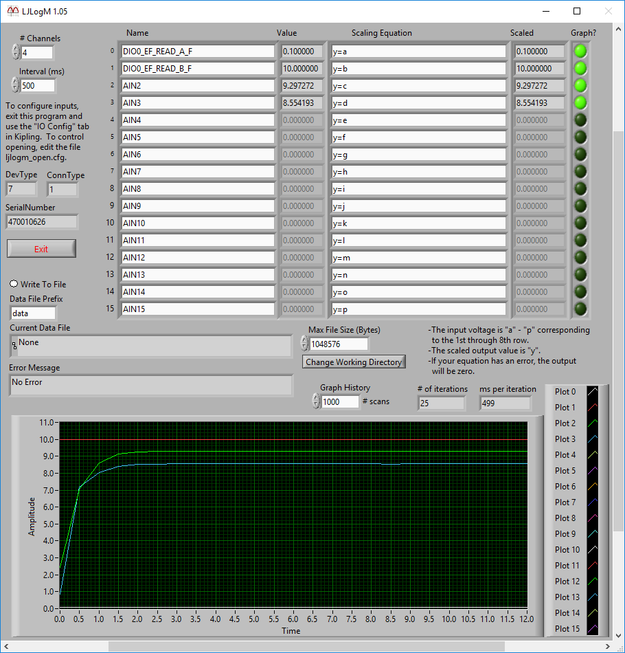
Once the frequency counter is enabled (above), you can read DIO0_EF_READ_A_F and DIO0_EF_READ_B_F using any row in LJLogM.
Reading a Frequency in LJStreamM
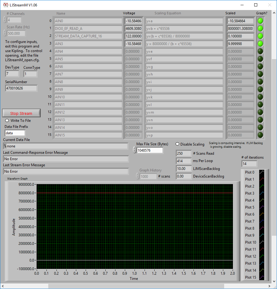
Once the frequency feature is enabled (above), you can read DIO0_EF_READ_A which returns the period in clock ticks (in stream mode only the integer values DIO0_EF_READ_A and DIO0_EF_READ_B can be read). To get the period in seconds, divide by the clock frequency.
In stream mode DIO0_EF_READ_A only returns the lower 16-bits, so if you want the upper 16-bits you need to also read STREAM_DATA_CAPTURE_16, which is mentioned on the LJLog/Stream Scaling Equations page.
In the following screenshot we read the lower 16-bits in row b and the upper 16-bits in row c, so the applicable equations are:
y = b + c*65536 // total ticks
y=(b + c*65536) / 80000000 // period in seconds
y = 80000000 / (b + c*65536) // frequency in Hz
Reading a Frequency in DAQFactory
To configure the feature you can use steps 1-5 above or write DIO_EF_CLOCK0_ENABLE = 1, DIO0_EF_INDEX = 3, and DIO0_EF_ENABLE = 1 in DAQFactory. See "Device Configuration" on the DAQFactory for LJM page.
To read the period value you need to read DIO0_EF_READ_A_F. Invert that value to get Hz, or you can also read DIO0_EF_READ_B_F. See "Linking LabJack Inputs/Outputs to DAQFactory Channels" on the DAQFactory for LJM page.
Reading a Frequency in Your Program
To configure the feature you can use steps 1-5 above or write DIO_EF_CLOCK0_ENABLE = 1, DIO0_EF_INDEX = 3, and DIO0_EF_ENABLE = 1 in your program. You can do this with a few calls to eWriteName or a single call to eWriteNames.
To read the period value read DIO0_EF_READ_A_F. You can do this with a call to eReadName. Invert that value to get Hz, or you can also read DIO0_EF_READ_B_F. Note that the register DIO0_EF_READ_B_F is a capture register, and thus it is only updated whenever the DIO0_EF_READ_A register is read. If using stream mode you also need to read STREAM_DATA_CAPTURE_16 if you want the upper 16-bits.
In the applicable LJM example archive, look for an example called "Write Read Loop with Config" that can be used to configure and read the timer.
