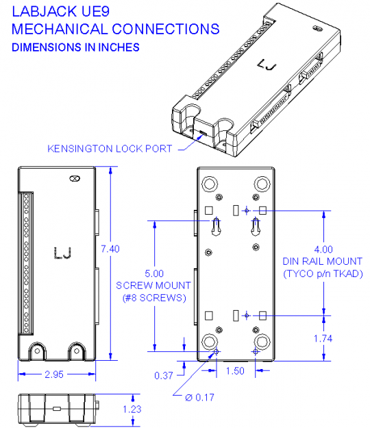
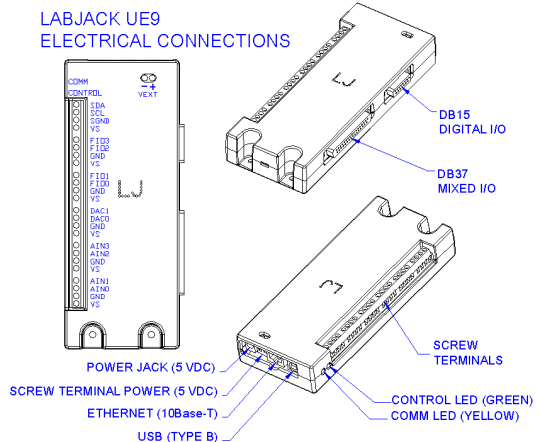
See below drawings of the UE9.
The square holes on the back of the enclosure are for DIN rail mounting adapters (TE Connectivity part #TKAD).
CAD drawings of the UE9 enclosure are attached to the bottom of this page. (DWG, DXF, IGES, STEP)
The UE9 enclosure base has a pair of slotted holes towards the communication end (left in below drawing), and another pair of mounting holes at the opposite end (right in below drawing).
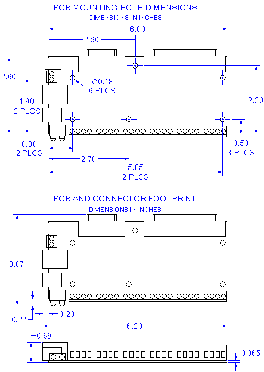
UE9 OEM PCB Dimensions
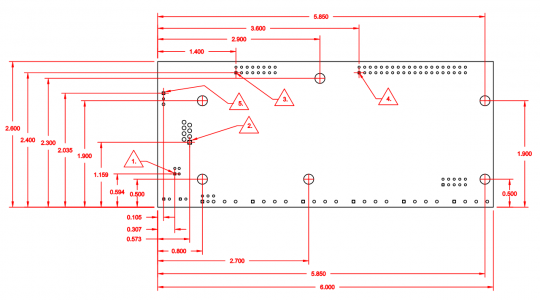
Notes on OEM PCB Dimensions
-
USB, PIN 4
-
ETHERNET, PIN 1
-
OEM 2X8 HEADER, 0.100" PITCH, PIN 1
-
OEM 2X20 HEADER, 0.100" PITCH, PIN 1
-
VEXT, PIN 1
More Details
See the OEM page for details on connector pin-headers and more.
Common neutral format CAD models are provided below. Right-click and select the "Save link as..." option to download STEP files.